I spent six weeks blaming my Voron 2.4 for prints that came out fine, just not great. The corners had little bulges. The top surface looked slightly pillowed. Stringing on PETG no matter how I tuned retraction. I rebuilt the toolhead, replaced the hotend, even swapped the motherboard. None of it fixed anything.
The fix was a flow ratio of 0.96 instead of 1.00, a pressure advance of 0.038 instead of the printer-default 0.05, and a max volumetric speed cap that I’d never set so OrcaSlicer was overrunning my hotend by about 30%. Three calibrations. About four hours of test prints. The “bad printer” turned out to be perfectly fine.
This is the guide I wish someone had handed me before week one. It covers every calibration in OrcaSlicer’s Calibration menu, in the order I actually run them, with the values you’ll probably land on for the common filaments. Written against OrcaSlicer v2.3.2, the current stable build (13.7k GitHub stars at the time of writing).
Why calibrate at all?
OrcaSlicer ships with sensible defaults for most printers. If you just want to print PLA Benchies, the defaults usually work. So why does the rabbit hole exist?
Because every printer has small mechanical tolerances. Every filament has different rheology. Every hotend has a slightly different thermistor offset. The defaults assume “average everything”, and most prints end up averagely-okay. Calibration replaces those averages with the actual numbers for your rig and this spool.
What you get from a few hours of calibration:
- Stringing drops from “have to clean every print” to “occasional whiskers”
- Top surfaces stop pillowing and start looking smooth like injection-moulded parts
- Sharp corners stop bulging or losing material
- Dimensional accuracy good enough to print bearings, gears, and threaded parts that fit on the first try
- Print speed safely 30 to 50% higher because you know your hotend’s real flow ceiling
- Settings you can copy-paste between filament brands without re-discovering them
The calibration suite is the single biggest reason power users choose OrcaSlicer over Bambu Studio. Bambu Studio ships with two calibrations (Flow Dynamics and Flow Rate). OrcaSlicer ships with at least nine. That’s not a marketing number, it’s the actual menu count when you open Calibration in v2.3.2.
The order debate (and what to actually do)
Here’s the thing nobody tells you up front: the OrcaSlicer wiki and the most-shared online guides give different orders. This is not a small disagreement.
The Calibration menu inside the app lists the tests in this sequence: Temperature, Flow Rate, Pressure Advance, Max Volumetric Speed, Retraction, Tolerance, Cornering, Input Shaping, VFA. The official wiki Calibration Guide page suggests almost the same. But search “OrcaSlicer calibration order” on Reddit or any of the dozen tutorial blogs and you’ll see this instead: Temperature, Flow Ratio, Pressure Advance, Retraction. Volumetric Speed and the rest get tacked on at the end as “advanced”.
I’ve gone through GitHub Discussion #2476 where a user asked SoftFever directly which order to follow. The maintainer never posted a definitive answer. The top-voted community reply admits “the tests likely interact, you might want to re-run after each major change.” That’s the honest version.
Here’s what I do, and what most successful Voron and Bambu users I know also do. Treat calibration in three stages, not as a flat list:
Stage 0 (hardware, not OrcaSlicer): bed level, Z-offset, e-steps or rotation_distance. If these are wrong, every other calibration will lie to you.
Stage 1 (per filament): Temperature Tower, Max Volumetric Speed, Flow Ratio, Pressure Advance, Retraction. Run these every time you switch to a new spool brand or color. Maybe twenty minutes of slicing time, an hour of print time.
Stage 2 (per filament, optional): Tolerance Test. Only matters if you’re printing functional parts that need to fit. Skip for cosmetic prints.
Stage 3 (per printer, once or after mechanical changes): Cornering, Input Shaping, VFA. These tune the printer’s motion system. They don’t change with filament.
If you only have time for three calibrations, do Temperature, Flow Ratio, and Pressure Advance. That’ll cover ninety percent of “my prints look bad” complaints. Everything else is polish.
Stage 0: the hardware basics OrcaSlicer can’t fix
Don’t skip these. I’ve watched people run six rounds of flow rate calibration trying to figure out why nothing converges, when the real problem was their extruder’s rotation_distance was off by 5%.
Bed level: print a flat 100mm square at 0.2mm layer height. If any corner shows a different first-layer squish than the others, your bed isn’t level. Re-mesh. Modern Bambu, Creality K-series, Prusa MK4, and Voron with KAMP all auto-mesh on each print, so this is mostly handled. On older machines, run a manual mesh.
Z-offset: the gap between nozzle and bed on layer one. Too high and your first layer doesn’t stick. Too low and the nozzle scrapes plastic into the bed. The “paper test” works fine for getting close (slide paper under the nozzle, adjust until it drags slightly). Live-tune from there during the first layer of a calibration print.
E-steps (Marlin) or rotation_distance (Klipper): tell the firmware exactly how much filament one motor revolution pushes. Set extruder to push 100mm of filament with the hot end at temperature, measure how much actually pushed (mark the filament before, measure with calipers after), and adjust the firmware variable proportionally. This is upstream of OrcaSlicer’s flow ratio. If e-steps are wrong, flow ratio just compensates badly.
Calibration: Temperature Tower
Path: Calibration → Temperature
What it fixes: the optimal hotend temperature for this exact filament. Brand and color both matter. Black PLA from Brand A often runs five to ten degrees different from white PLA from Brand B because of pigment additives. The defaults in the filament profile are reasonable starting points, not destinations.
OrcaSlicer pre-fills a sensible range when you pick a filament: 180 to 230°C for PLA, 220 to 250°C for PETG, 230 to 270°C for ABS, 220 to 245°C for TPU. Each tower segment is 5°C. Print the whole thing, let it cool for ten minutes, then inspect.
What you’re looking for, top to bottom:
- Stringing between the pillars (less stringing = better)
- Surface finish on the flat faces (smoother = better)
- Layer adhesion (try snapping a segment with pliers, the layer that breaks should look like a clean fracture, not delaminate cleanly)
- Bridge sag on the overhang feature (less sag = better)
- Any temperature-related defects like blobs, bubbling, or oozing
Pick the lowest temperature where layer adhesion is still solid and stringing looks acceptable. Going lower reduces oozing and improves overhangs. Going higher improves layer bonding but worsens stringing. Tied results, pick the lower number.
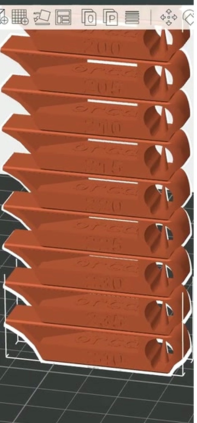
Common landing zones for a 0.4mm nozzle:
- PLA: 200 to 215°C (Bambu PLA Basic typically 210, Polymaker PolyTerra 205)
- PETG: 235 to 245°C (240 is the most common landing)
- ABS: 240 to 250°C
- ASA: 245 to 255°C
- TPU 95A: 220 to 235°C
Gotcha: the default 5°C step is too coarse for high-speed printing where 2 or 3°C swings genuinely change quality. Override start, end, and step manually for fine work. Second gotcha: if your hotend has a poor PID tune, every block prints inconsistently and the tower lies. Run a PID tune on the printer firmware first if you suspect drift.
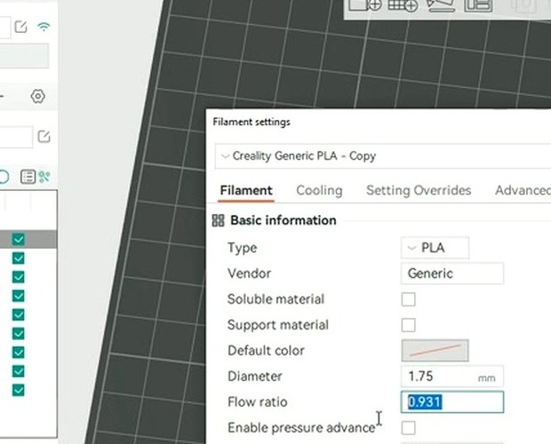
Calibration: Flow Rate (use YOLO, not the old two-pass method)
Path: Calibration → Flow Rate → YOLO (Recommended) or Pass 1 / Pass 2
Flow rate is the extrusion multiplier. Set it wrong and your entire print is over- or under-extruded by a few percent, which shows as either pillowy ridges on top surfaces (over) or pinhole gaps and weak walls (under).
OrcaSlicer rewrote the flow rate test in PR #6479 for v2.3.0. The new method, called YOLO, replaces the older two-pass method for almost everyone. YOLO prints eleven blocks in a single test, each with a flow modifier from minus 0.05 to plus 0.05 in 0.01 steps. The top surface uses an Archimedean chord pattern (replaced the old Monotonic Line) which makes flow errors more visible.
The procedure is dead simple:
- Pick “YOLO Recommended”
- Print the eleven-block array
- Look across the top surfaces. Find the smoothest one. Read the printed modifier label, like “+0.02”
- Add that modifier to your current flow ratio. Current 1.00, best block “+0.02”, new flow = 1.02
- Save the new value in your filament profile
That’s it. No formulas. No conversions. The old Pass 1 plus Pass 2 method (which used the formula NewFlow = OldFlow × (100 + modifier) / 100, run twice, ninety minutes total) is still available if you want it. SoftFever specifically recommends saving Pass 1 plus Pass 2 for silk PLA, dual-color PLA, and other “picky” filaments where the YOLO step of 0.01 is too coarse.
YOLO Perfectionist is a third option: range minus 0.04 to plus 0.035, step 0.005. SoftFever notes most users won’t perceive 0.005 increments, so this is overkill except for the same picky filaments.
What you’ll typically land on for a 0.4mm nozzle:
- PLA generic: 0.95 to 1.00
- PLA silk or dual-color: 0.92 to 0.98
- PETG: 0.93 to 0.98 (PETG runs slightly under-extruded out of the box on most profiles)
- ABS or ASA: 0.97 to 1.01
- TPU 95A: 0.95 to 1.05 (high spool-to-spool variance)
Two important gotchas. First, recent OrcaSlicer builds use your active layer height for the calibration prints, but older builds hardcoded 0.2mm. If you’re on an older Orca, change to 0.2mm before running flow rate so the result matches what you actually print. Second, the objective method (print a single-wall cube, measure walls with calipers, target equals nozzle width) is the gold-standard tiebreaker if two YOLO blocks look equally good. Formula: NewFlow = (TargetWallThickness / MeasuredWallThickness) × CurrentFlow. Aim for less than 3% deviation.
Calibration: Pressure Advance
Path: Calibration → Pressure Advance → Line / Pattern / Tower / Adaptive
Pressure Advance compensates for the lag between extruder rotation and material exit at the nozzle. Without it, fast accelerations into a corner over-extrude (because the melt zone is still pressurised) and decelerations after the corner under-extrude (because the pressure drops). The visible symptoms: bulges right at corner exits, gaps right after corners, “fat” external corners on cube prints, and missing material at line starts.
Klipper calls the parameter pressure_advance. Marlin and RepRapFirmware call the same concept “K-factor” or “Linear Advance”. OrcaSlicer’s dialog auto-detects which firmware you’re running in v2.3.2 and labels accordingly. The numbers are different between extruder geometries:
- Direct drive: typically 0.0 to 0.1
- Bowden: typically 0.4 to 1.0 (the long PTFE tube creates much more pressure lag)
OrcaSlicer offers four PA test methods. They’re not equivalent. Pick based on what you need.
Line method. Prints parallel lines at increasing PA values along the bed. Pick the cleanest line, read the value, save. Quick (about ten minutes) but its accuracy depends entirely on first-layer quality. If your bed isn’t level or your Z-offset is off, the line method gives a wrong answer. Best used as a five-minute sanity check after a more thorough method.
Pattern method. Ellis’ pattern test (from Ellis’ Print Tuning Guide, ellis3dp.com), ported to OrcaSlicer. Prints prism-like patterns. You pick the segment with the sharpest corners and fewest gaps or bulges. Removes first-layer dependency. This is the most accurate quick method, and the one I run first on every new filament. Re-run with a narrower range if you want to refine.
Tower method. PA increases linearly with Z height. Step values matter: 0.002 per mm for direct drive, 0.02 per mm for Bowden. Print at 120 mm/s or higher so the PA effect actually shows. Mark the height where corners look cleanest, multiply by the step. Slowest method (45-minute print) but completely first-layer independent.
Adaptive Pressure Advance. Added in 2.3.x, accessible via PR #5609. This runs PA tests at multiple flow rates and accelerations, then OrcaSlicer fits a model that emits the right PA for any given feature during your print. It’s overkill for stock printers. It’s exactly right for high-flow CoreXY rigs where flow ranges from 5 mm³/s on outer walls to 28 mm³/s on infill.
What you’ll typically land on for a 0.4mm direct-drive setup:
- PLA: 0.025 to 0.040
- PETG: 0.035 to 0.055
- ABS: 0.030 to 0.050
- TPU 95A: 0.05 to 0.08
Bowden values run roughly double these.
One quality-of-life note: in earlier OrcaSlicer builds, the Input Shaping and Cornering tests were zeroing out PA for the duration of the test, which faked the result. The fix landed in a recent release. If your IS test results look weird and you’re on an older Orca, update first, then retest.
Final tip: PA changes when filament moisture changes, when hotend temperature changes, when the nozzle wears, and after Input Shaping changes. Re-run after any of those. If you’re between two PA values and unsure, pick the lower one. High PA causes worse artifacts than low PA.
Calibration: Max Volumetric Speed
Path: Calibration → More → Max Volumetric Speed
Every hotend has a melt-rate ceiling. Push past it and you get under-extrusion no matter what speed or PA you set, because the filament can’t melt fast enough to keep up. The Max Volumetric Speed test finds that ceiling so OrcaSlicer can clamp print speeds intelligently.
OrcaSlicer generates a tower or single-wall test that ramps from a start flow (default 5 mm³/s) to an end flow (default 20 mm³/s) at 0.5 mm³/s per millimetre of Z height. Print, then scan up the tower for the height where the surface visibly degrades. The gloss disappears, gaps appear, the wall feels rough.
Calculate: MaxFlow = StartFlow + (failure_height_mm × step). Failure at 17mm with 5 start and 0.5 step gives 13.5 mm³/s.
Then subtract a 10 to 20% safety margin before saving. Always. Pushing right at the ceiling means any small variation (cold day, slightly wet filament, slightly worn nozzle) tips you into under-extrusion.
Stock 0.4mm hotend ceilings, after the safety margin:
- PLA: save 12 to 15 mm³/s (real ceiling 14 to 18)
- PETG: 6 to 8 (real 7 to 10)
- ABS: 7 to 10 (real 8 to 12)
- TPU 95A: 4 to 6 (real 4 to 8)
High-flow hotends (Bambu, Revo HF, Volcano, CHT clones) shift these up roughly 1.5 to 2 times. Bambu’s stock 0.4mm hotend is officially rated 32 mm³/s but realistic in field tests is 20 to 24. Don’t trust manufacturer numbers, run the test.
This is the speed ceiling, not your print speed. Your real print speed equals volumetric_speed / (line_width × layer_height). So a 12 mm³/s ceiling at 0.4mm line width and 0.2mm layer height gives a 150 mm/s wall speed. Push the slicer’s wall speed any higher and OrcaSlicer will silently clamp it back to volumetric.
Calibration: Retraction
Path: Calibration → Retraction Test
Retraction pulls filament back during travel moves to stop oozing. Get it wrong and you have either strings between every feature (too little retraction) or clogs, grinding, heat creep, and missing material at line starts (too much).
The test prints a tower of small posts. Each segment uses a different retraction length. The defaults are tuned to extruder geometry: direct drive runs 0 to 2mm in 0.1mm steps, Bowden runs 1 to 6mm in 0.5mm steps. Pick the shortest length that has no strings between the posts AND no surface defects on the posts themselves (look for pock-marks, voids).
If the best segment is the third notch from the base with a 0.1mm step starting at zero, your optimal retraction is 0.3mm.
Common landing values:
- PLA direct drive: 0.2 to 0.6mm at 35 to 50 mm/s
- PLA Bowden: 3 to 5mm at 40 mm/s
- PETG direct: 0.6 to 1.2mm at 25 to 40 mm/s
- PETG Bowden: 4 to 7mm at 30 mm/s
- ABS direct: 0.4 to 0.8mm at 35 to 50 mm/s
- TPU direct: 0.5 to 1.5mm at 20 to 30 mm/s (Bowden retraction on TPU is generally a bad idea)
The single biggest gotcha: if stringing persists after a “perfect” retraction, the real culprit is moisture, not retraction. PETG, ABS, Nylon, and TPU all string heavily when wet. Dry the filament first (60 to 65°C for six to eight hours for PETG; 80 to 95°C for eight to twelve hours for Nylon), then retest. I’ve watched people raise retraction to 8mm trying to fix wet PETG and end up with a clogged Bowden tube.
Two minor settings that compound retraction:
- Z-hop 0.2 to 0.4mm helps with complex prints but slows the print noticeably
- “Wipe while retracting” reduces seam blobs and works well with low retraction values
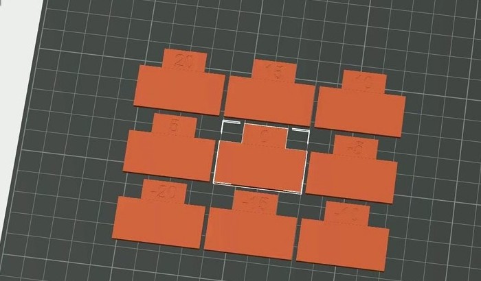
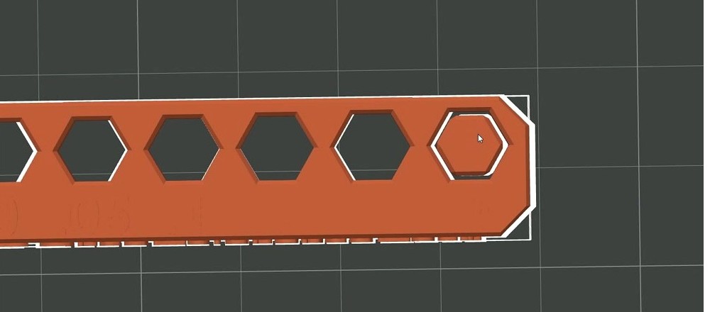
Calibration: Tolerance Test
Path: Calibration → More → Orca Tolerance Test
This one only matters if you’re printing functional parts that need to fit. Skip if all your prints are decorative.
The test prints a base with six hexagonal holes at 0.0, 0.05, 0.1, 0.2, 0.3, and 0.4mm tolerance, plus a hex tester piece. The tester is sized to match the hole sizes. The smallest hole the tester slides into snugly (smooth, no slop, slight resistance) tells you your printer’s effective tolerance for that filament.
Critical gotcha: set xy_hole_compensation and xy_contour_compensation to zero before running this test. Otherwise you’re measuring compensation, not reality. Both settings live under Process → Quality → Precision.
Reading the result:
- Tester fits the 0.2mm hole snugly: your printer is about 0.2mm tight on holes for this filament
- Holes feel too small (tester only fits 0.3 or 0.4): set positive xy_hole_compensation, typically plus 0.05 to plus 0.15mm
- Holes feel too large (tester slops in 0.0 hole): negative compensation
Common results:
- PLA: 0 to plus 0.05mm compensation
- PETG: plus 0.05 to plus 0.15mm (PETG shrinks holes more than PLA)
- ABS: minus 0.05 to plus 0.05mm depending on your enclosure setup
- TPU: plus 0.10mm or more, highly variable
An M6 Allen key works as a poor-man’s tester if you’ve lost the hex tester piece. Note that this test only covers Z-axis holes. Holes printed in different orientations (top-down vs side) shrink differently because of the layer stacking. For functional parts that need precise side-holes, you’d add a separate compensation routine.
Calibration: Cornering
Path: Calibration → More → Cornering
The dialog is firmware-aware in recent OrcaSlicer builds, validates that test acceleration is greater than test speed (a previous bug allowed nonsense values), and keeps PA active during the test (it had been getting reset to zero, faking results). If you’re on an older Orca, update before running this one.
What it tunes depends on your firmware:
- Marlin:
junction_deviation_mm(modern) or classic Jerk (legacy) - Klipper:
square_corner_velocity - RepRapFirmware: jerk values in mm/min
The test prints a tower with high acceleration (2000 mm/s² or more) and high speed (100 mm/s or more) using opaque high-gloss filament so ringing is visible. Each segment uses an increasing JD or jerk value. Find the height where corners start losing sharpness, and that’s your usable max.
Common landings:
- Marlin junction_deviation_mm: 0.02 to 0.08
- Klipper square_corner_velocity: 5 mm/s (the Klipper docs explicitly recommend not exceeding 5 when using input shapers)
- Marlin classic Jerk: 8 to 12 mm/s
- RRF jerk: 600 to 1000 mm/min
One last gotcha: restore your normal printer settings after running this test. The high-acceleration values used during the test will damage real prints if you forget.
Calibration: Input Shaping
Path: Calibration → More → Input Shaping
Input shaping cancels the resonance frequencies in your printer’s frame and gantry. Without it, a sharp acceleration into a corner sets the printer’s frame ringing at its natural frequency, which shows up as ghosting and echoes after every corner on your prints. With it tuned, those ripples disappear and you can run accelerations 30 to 50% higher without losing surface quality.
Firmware support is uneven:
- Klipper: native, with the firmware command
SHAPER_CALIBRATEavailable if you have an ADXL345 or MPU6050 accelerometer attached - Marlin 2.x: supported in recent builds
- RepRapFirmware: supported
- Bambu firmware (X1, P1, A1): handles input shaping automatically per print, no OrcaSlicer test needed
The OrcaSlicer test runs in two stages. The frequency test prints X-axis and Y-axis test towers across 15 to 110 Hz. Measure the height where ringing minimises, read off the frequency value labeled in OrcaSlicer. The damping test takes those frequencies and prints a damping test across 0.05 to 0.20 damping ratio. Default starting damping is 0.1.
OrcaSlicer’s dialog lets you pick a shaper type. The choice matters:
- MZV: most users, low ringing residue. Default and recommended starting point.
- EI: more aggressive smoothing. Specifically recommended for Delta printers.
- ZV: simpler and faster, less aggressive cancellation. Used when you want the smoothing without the throughput penalty.
- ZVD: a slightly more aggressive variant of ZV. Cancels two oscillation cycles instead of one.
- 2HUMP_EI and 3HUMP_EI: Klipper-only. Used for printers with two or three resonance peaks (rare).
Common values from real-world Klipper installs:
- Voron 2.4: X 50 to 70 Hz, Y 40 to 60 Hz
- Stock Ender 3: X 30 to 45 Hz, Y 25 to 35 Hz
- Bambu P1S (auto-tuned by firmware): X around 60, Y around 50
- Creality K1 / K1 Max: X 50 to 80, Y 40 to 70
Once you have values, update your Klipper printer.cfg’s [input_shaper] section with the new shaper_freq_x and shaper_freq_y values, then restart Klipper.
An ADXL345 accelerometer is dramatically more accurate than the visual print method. It costs about $5, mounts to the toolhead, and Klipper’s SHAPER_CALIBRATE command runs the whole sweep in three minutes per axis. If you do any serious printing on a Klipper machine, get one.
Re-run input shaping once a year, or after any mechanical change: belt tension, frame mods, new toolhead, even a heavy spool change. The Klipper docs say “once a year” as a maintenance cadence and that’s about right.
Calibration: VFA (Vertical Fine Artifacts)
Path: Calibration → More → VFA Test
VFA stands for Vertical Fine Artifacts. The test identifies print speeds where stepper motor resonance creates fine vertical ripples on walls, sometimes called Motor Resonance Rippling or MRR. Different from ringing: VFA persists across the entire wall and doesn’t fade with distance from corners.
The test prints a tower with angled walls while increasing speed per segment (defaults around 160 mm/s start, 500 mm/s end, 20 mm/s step). Inspect for the highest speed where vertical ripples are still acceptable. Calculate optimal speed: start + (failure_notch × step).
This one runs LAST in the calibration sequence. PA, flow, and Input Shaping all interact with what you’d interpret as VFA. Run them first, then VFA tells you what speeds the printer’s stepper system genuinely can’t handle without resonance.
Common landings:
- Stock Ender or bedslinger: 200 to 250 mm/s wall speed
- Bambu P1 or X1, Voron, Creality K-series: 250 to 350 mm/s
- Tuned high-flow CoreXY: 350 to 500 mm/s
If your X and Y axes differ in resonance bands, run VFA on the worse axis. Recent Bambu A1 firmware has built-in VFA mitigations that may mask the test result.
Sidebar: Bambu printer auto-calibration (and why P1 owners still need this guide)
If you own a Bambu Lab printer, here’s the catch: auto-calibration capability differs by model.
- X1 series and H2D: LiDAR-based Flow Dynamics calibration runs automatically before each print. Bambu’s lidar measures the actual extrusion in real time and tunes pressure advance live. This is excellent within its scope.
- A1 and A1 Mini: eddy-current Flow Dynamics, requires firmware 01.04 or newer. Same idea, slightly less accurate than lidar but still automatic.
- P1S and P1P: manual only. Bambu Studio offers Flow Rate and Flow Dynamics tests, but you have to run them by hand for each filament. This is the single biggest reason P1 owners gravitate to OrcaSlicer.
OrcaSlicer’s manual calibration suite gives P1 owners feature parity with X1 owners (and then some, because OrcaSlicer adds temperature, max volumetric speed, retraction, tolerance, cornering, input shaping, and VFA tests on top). The Bambu Studio path is simpler but leaves quality on the table for non-X1 owners.
Note that since the January 2025 firmware Authorization Control update, OrcaSlicer connects to Bambu printers only via LAN Mode plus Developer Mode. Cloud printing through OrcaSlicer is not currently supported. The calibration tests still run fine on LAN.
The filament cheatsheet (after calibration)
Once you’ve run the calibration suite for a filament, here’s where the values typically land. Use this as a sanity check, not a replacement for actually running the tests.
| Filament | Nozzle | Bed | Flow ratio | Max vol | PA (DDE) | Retraction (DDE) |
|---|---|---|---|---|---|---|
| PLA | 200 to 215°C | 55 to 65°C | 0.95 to 1.00 | 14 to 18 mm³/s | 0.025 to 0.040 | 0.2 to 0.6mm @ 35 to 50 |
| PETG | 235 to 245°C | 75 to 85°C | 0.93 to 0.98 | 7 to 10 | 0.035 to 0.055 | 0.6 to 1.2mm @ 25 to 40 |
| ABS / ASA | 240 to 250°C | 100 to 110°C | 0.97 to 1.01 | 8 to 12 | 0.030 to 0.050 | 0.4 to 0.8mm @ 35 to 50 |
| TPU 95A | 220 to 235°C | 40 to 60°C | 0.95 to 1.05 | 4 to 8 | 0.05 to 0.08 | 0.5 to 1.5mm @ 20 to 30 |
| PC blend | 250 to 270°C | 100 to 120°C | 0.97 to 1.01 | 6 to 10 | 0.025 to 0.045 | 1 to 3mm @ 30 to 45 |
| PA-CF | 270 to 290°C | 90 to 110°C | 0.97 to 1.01 | 8 to 12 | 0.025 to 0.040 | 1 to 3mm @ 25 to 35 |
Bowden retraction values run roughly 4 to 6 times higher than the direct-drive numbers above.
Troubleshooting common calibration hiccups
“My YOLO flow rate keeps drifting between spools of the same brand.” Spool-to-spool variance is real, usually 1 to 2%. Recalibrate per spool for parts that need accuracy.
“Pattern method PA looks great but my real prints still bulge at corners.” The pattern-method optimum often reads slightly low. Try the value just above the one you picked, print a test cube, compare.
“I ran retraction calibration but PETG still strings.” The filament is wet. Retraction is the last knob to tune for stringing, not the first. Dry it for six hours at 65°C and retest.
“Tolerance test holes are tight on PLA but loose on PETG.” That’s normal. PETG shrinks more than PLA in the X-Y plane. Set xy_hole_compensation per filament profile, not globally.
“My input shaping print looks the same at every frequency.” Either your printer’s resonance is below the test range (unlikely on modern printers), or your acceleration is too low to excite resonance during the test. Bump test acceleration to 5000 mm/s² or higher and rerun.
“The calibration menu only shows two options on my Bambu Studio.” That’s expected, you’re running Bambu Studio, not OrcaSlicer. Bambu Studio ships only Flow Rate and Flow Dynamics. The other seven calibrations are OrcaSlicer-only. Switch slicers if you want the full suite.
“My Klipper input_shaper section says shaper_freq_x = 0 after I save.” You have to manually update printer.cfg, OrcaSlicer doesn’t write the firmware config. Open Mainsail or Fluidd, edit printer.cfg, paste your X and Y values into the [input_shaper] block, restart Klipper.
FAQ
What order should I run OrcaSlicer’s calibrations?
The official wiki and the most-shared online guides disagree. The honest answer (per GitHub Discussion #2476) is that the tests interact, no single order is provably “right”, and re-running after major changes is part of the process. The pragmatic order most users land on: bed level and Z-offset first, then per-filament Temperature → Max Vol Speed → Flow Ratio → Pressure Advance → Retraction. Tolerance only if you need functional parts. Cornering, Input Shaping, and VFA once per printer.
How often do I need to re-calibrate?
Per filament for temperature, flow ratio, pressure advance, and retraction. Per filament family for tolerance. Once per printer (or after mechanical changes) for cornering, input shaping, and VFA. New nozzle, new hotend, or major firmware change resets pretty much everything.
Should I use YOLO flow rate or the older Pass 1 plus Pass 2?
YOLO for almost everything. Pass 1 plus Pass 2 only for silk PLA, dual-color PLA, or other “picky” filaments where the YOLO 0.01 step is too coarse. SoftFever’s PR #6479 spelled this out explicitly.
What’s the difference between Pressure Advance line, pattern, and tower methods?
Line is fast but depends on first-layer quality. Pattern is the most accurate quick method (run this first). Tower is slow but completely first-layer-independent. Adaptive PA fits a model across flow and acceleration ranges, useful only for high-flow CoreXY printers.
Does OrcaSlicer’s input shaping replace Klipper’s SHAPER_CALIBRATE?
Not really. Klipper’s SHAPER_CALIBRATE with an ADXL345 accelerometer is the gold standard. OrcaSlicer’s visual print method is a fallback for users without an accelerometer. If you have an accelerometer, use SHAPER_CALIBRATE.
Why is my Bambu P1S not showing input shaping in OrcaSlicer’s calibration menu?
Bambu firmware handles input shaping automatically per print on X1, P1, and A1 series. OrcaSlicer correctly hides the test for those printers because it can’t override the firmware-side value. Not a bug.
Do I need to dry filament before calibrating?
Yes. Wet filament fakes every calibration result. Dry per material (PLA 50°C 6h, PETG 65°C 8h, Nylon 80°C 12h) before running the suite, especially if the spool has been open more than two weeks.
Wrap-up
The whole calibration suite from a fresh filament takes about three hours of print time and maybe forty-five minutes of active work. Once you’ve done it, your prints will look measurably better and your slicer settings stop being guesses. The values you save in your filament profile travel with the spool across machines, which means a calibrated filament profile is a one-time investment per spool brand and color.
If you’re new to OrcaSlicer, start with the beginners guide and get your first print done before diving into calibration. If something’s failing in ways the calibration suite doesn’t fix, the troubleshooting guide covers the common slicer-side bugs and connectivity issues. And if you don’t have OrcaSlicer installed yet, grab it from the download page.