I keep the OrcaSlicer Process panel pinned to a second monitor while I slice. Not because I tweak everything, but because the panel has six tabs and somewhere around four hundred individual settings, and the answer to “where does that thing live” is genuinely not always obvious. The tab labels are accurate, but tabs sometimes overlap. Quality holds layer height and seam, but Speed holds the speeds that affect quality. Support sits between Strength and Multimaterial. Brim is in Others, not Strength.
This guide is the panel reference I wish I’d had when I first opened OrcaSlicer. It walks through every Process tab, names every setting that matters, explains what it actually does in one or two plain sentences, and points out the thirty most-misunderstood toggles. Written against OrcaSlicer v2.3.2, the current stable build with 13.7k GitHub stars, current as of writing.
It’s organised by Process panel tab, with deep dives on the settings beginners and intermediate users actually search for. At the end is the profile-hierarchy explainer (Printer settings vs Filament settings vs Process settings, which override which) and a frequently-asked-questions section.
How the Process panel is laid out
The Process panel sits below the Printer and Filament selectors in OrcaSlicer’s right sidebar. It has six tabs across the top, left to right: Quality, Strength, Speed, Support, Multimaterial, Others. You’ll spend most of your time on Quality, Strength, and Speed.
Two important details before diving in. First, the panel has a mode toggle at the bottom-left labelled Simple, Advanced, or Developer. Many of the settings below are only visible in Advanced mode. A handful are Developer-only. If you can’t find a setting, switch modes. Second, the colored chip in the panel header tells you whether the current settings match the saved profile. When the dot’s showing, your tweak is unsaved; it’ll print, but won’t survive switching profiles.
Quality tab
The Quality tab is the geometry-of-extrusion tab. It’s where you tune how the slicer actually puts plastic down: layer height, line width, where seams go, and the precision settings that affect dimensional accuracy.
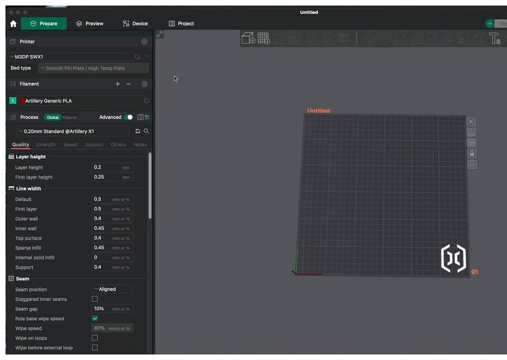
Layer height and first layer height
Layer height is the single most impactful slider in the entire slicer. OrcaSlicer’s wiki recommends 20% to 80% of nozzle diameter; for a 0.4mm nozzle that means 0.08mm to 0.32mm. The 0.20mm default is the sweet spot for most prints. Drop to 0.12mm for fine detail (figurines, miniatures), bump to 0.28mm for fast prints where surface quality doesn’t matter.
First layer height is typically larger than the rest of the print, around 0.20-0.24mm. A larger first layer is more forgiving to bed level imperfections.
Line width (eight separate sliders)
Line width has eight independent fields: default, first layer, outer wall, inner wall, top surface, sparse infill, internal solid infill, and support. They all default to percentages of nozzle diameter. The wiki’s recommended starting points:
- Outer wall: 105 to 120% (slightly wider than nozzle for surface quality)
- Inner wall: 120% or higher (filling space between perimeters cleanly)
- Top surface: 100 to 105%
- Sparse infill: 115%
- Internal solid infill: 110%
- Support: 100%
Most users never touch these. They’re worth tuning when you have specific issues like top-layer pinholes (raise top surface line width) or thin internal walls separating from outer walls (raise inner wall).
Seam settings
Where each layer’s start point lives. Six options for seam position: Aligned (default, all seams stack on one vertical line), Aligned Back (same but biased to the back of the model), Nearest (per-layer-shortest-travel), Back (always at the back), Random (every layer different), and Painted (you brush where you want it in Prepare).
For most prints, Aligned plus painting where the seam should hide is the sweet spot. Random looks worse than people expect; the seam stays visible just spread out everywhere.
Staggered inner seams (Advanced mode) rotates the inner-wall seam start positions across layers so they don’t pile up directly under the outer seam. This is a free quality bump. The “smoosh” of stacked inner seams telegraphs through to the outer wall otherwise.
Scarf joint seam is OrcaSlicer’s signature feature. Instead of starting and ending each loop at a single Z-seam point, the slicer ramps the first and last segment over itself across multiple layers, like a wood scarf joint. The result is that on curved or organic surfaces, the seam essentially disappears. Slope length defaults to 20mm. Outer wall speed must be below 100mm/s for clean execution. Toggle “applied to inner walls” off unless you specifically want it; it adds slicing time without visible benefit.
Precision settings
The precision block is for parts that need to fit something else.
- Slice gap closing radius: how aggressively to close small gaps in the input mesh. Default 0.049mm. Touch only if a model has gaps the slicer is missing.
- Resolution: how finely to slice arc segments. Default 0.0125mm. Lower values produce smoother curves at the cost of larger G-code files.
- Arc fitting: replaces small straight segments with arc commands (G2/G3) when the firmware supports them. Smaller files, smoother curves on Klipper / Marlin 2.
- X-Y hole compensation: enlarges or shrinks holes only. Use when M3 holes won’t accept screws (typically +0.1mm to enlarge).
- X-Y contour compensation: changes outside profile dimensions. Different from hole comp.
- Elephant foot compensation: shrinks the bottom 1-5 layers inward to counteract first-layer squish bulge. 0.10-0.20mm typical. Crank if your prints look fat at the base.
- Precise wall: zeros the overlap between outer and inner walls (default has slight overlap). Improves dimensional accuracy by about 0.05mm. Enable for parts that need to fit something. Strength is unaffected per Orca’s docs. Known interaction bug with “only one wall on top”.
Wall generator: Classic vs Arachne
This is the big architectural choice. Classic uses fixed line width perimeters; if a feature is thinner than 2× line width, you get a gap. Arachne dynamically varies line width to fit thin features without leaving gaps. Arachne is the default for most modern profiles.
Pick Arachne for detailed or organic models where thin features matter. Pick Classic for boxy mechanical parts where predictability matters more than fit-to-shape adaptation. Arachne adds slicing time.
Walls and surfaces
- Only one wall on top surfaces: replaces the standard 2-loop top with a single loop, freeing surface area for top infill to fill cleanly. Best for prints with small letters, logos, or thin top features.
- Only one wall on first layer: similar idea for the bottom.
- Walls printing order: Inner/Outer/Inner gives the cleanest exterior (requires 3+ walls). Outer/Inner is fastest. Inner/Outer is the overhang-friendly default.
- Alternate extra wall (sandwich mode): adds an extra wall every other layer for stronger functional parts without doubling print time.
- Detect thin wall: for very thin features that don’t fit Arachne’s full line, prints them as gap-fill instead of a true wall.
Bridging
How the slicer handles overhangs of more than 45 degrees. Thick bridges sets the bridge layer’s flow ratio higher (1.0 default; some users set 0.95-1.05). Extra bridge layer (Advanced) adds a second bridge layer at higher density. Don’t filter out small internal bridges keeps tiny bridges that the slicer would otherwise replace with infill.
Ironing
Smooths top surfaces by re-running the nozzle across them with minimal extrusion. Type options: no ironing (default), top surfaces, topmost surface only, all solid layers. Pattern, flow (about 10% by default), line spacing (0.10mm default), inset, angle, speed (typically 30 mm/s, much slower than print speed).
Ironing adds significant print time. Use it for visible top surfaces, not for hidden ones.
Strength tab
The Strength tab governs material density and topology. This is where you trade print time for part strength.
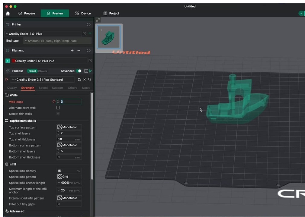
Wall loops and shell layers
Wall loops is the headline number. 2 is default, 3 is the pragmatic strength-per-print-time sweet spot, 4+ for functional parts. Top and bottom shell layers determine how thick the closed-off top and bottom are; defaults are usually 4 layers each.
Top shell thickness in mm overrides the layer count when layer height is large. Setting top shell layers to 4 on a 0.30mm layer height gives 1.2mm of solid material; if you’ve also specified 1.5mm minimum thickness, OrcaSlicer adds a fifth layer.
Sparse infill density and pattern
Density is famously misunderstood. 15% is enough for cosmetic prints, 25% for typical mechanical, and going above 40% produces diminishing returns vs just adding more walls. If your print needs more strength than 25% infill provides, raise wall loops first.
OrcaSlicer ships nearly thirty infill patterns. The ones that matter:
- Gyroid: mathematical isotropic infill. Equal strength all directions. Slower to slice and print but the gold standard for functional parts.
- Cubic: fast, strong, isotropic-ish. Best speed-to-strength tradeoff for most prints.
- Adaptive Cubic: densifies near walls and goes sparse in the middle. Saves material on big prints; same surface support as standard cubic.
- Lightning: generates support only directly under top surfaces, leaving the rest hollow. Print-time and material wins, but provides essentially no strength. Prototypes only.
- Lateral Honeycomb (NEW in v2.3.1): isotropic torsional stiffness with about 33% less weight than lateral lattice. Great for parts that bend.
- Tri-hexagon: classic strong-and-light pattern with three intersecting line directions.
- Concentric: rings following the outer shape. Used for flexible parts (TPU) where you want infill to flex with the wall.
Top surface pattern
How the topmost solid surface is filled. Monotonic Line gives the cleanest sheen. Concentric for circular features. Hilbert curve for a decorative pattern. Most users leave at Monotonic Line.
Infill anchor
Short connector segments tying infill ends into walls. Default percentage of line width. Touch only if infill visibly pulls away from walls.
Ensure vertical shell thickness
Auto-densifies infill near steep walls so vertical surfaces have proper material backing. Default on. Don’t disable unless you have a specific reason.
Speed tab
Speed has the most settings of any tab and the most opportunity to wreck a print. There are three blocks: print speeds (one per feature type), travel and acceleration, and the cornering / dynamics settings.
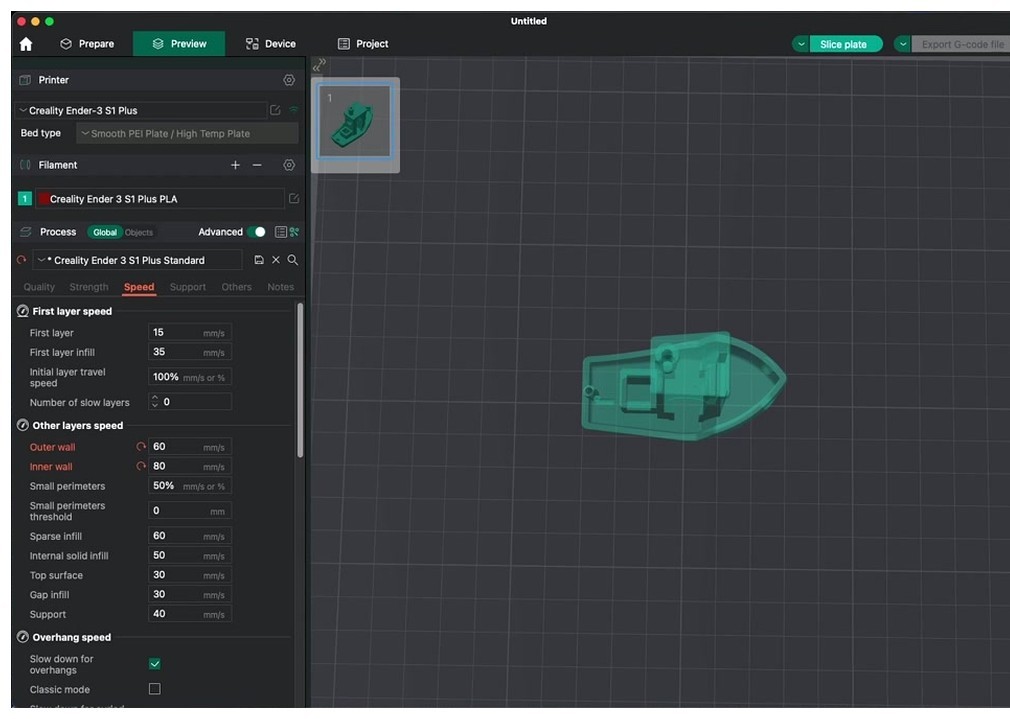
Print speeds
Each feature type has its own speed. Initial layer is the safety floor (default 50mm/s). Outer wall is the visible-quality lever (200mm/s on Bambu profiles, 60-80 typical for non-CoreXY printers). Inner wall can run 1.5 to 2× outer wall. Sparse infill is usually the highest speed ceiling, capped only by max volumetric flow.
Bridge speed (default 50mm/s) and support speed (default 150mm/s) are independent. Don’t try to push these high; bridge and support failures are the most expensive defects to recover from.
Travel speed
How fast the nozzle moves between extruding moves. Default 200-500mm/s depending on printer. High travel speed reduces stringing risk because filament has less time to ooze. Initial layer travel speed (Advanced) caps the first layer at a slower travel for safety.
Acceleration block
Default acceleration is the everything-else cap. Outer wall acceleration is the ringing/ghosting lever; the lower you set it, the cleaner sharp corners look. Inner wall, sparse infill, top surface, and travel each have their own.
For most users, the relevant tweak is outer wall acceleration. Stock 1500-2000 mm/s². Push lower (800-1200) for cleaner corners, push higher (3000-5000) for faster prints with worse ghosting.
Jerk, Junction Deviation, square_corner_velocity
Three flavors of “how aggressively does the printer round corners”. They model the same thing in different firmware:
- Marlin classic: jerk, in mm/s. Typical 8-12.
- Marlin 2.0+: junction deviation in mm. Typical 0.012.
- Klipper: square_corner_velocity in mm/s. Typical 5 (Klipper docs explicitly recommend not exceeding 5 with input shapers active).
Pick whichever your firmware supports. OrcaSlicer translates internally.
Pressure advance speed adjustment
Klipper-leaning Advanced setting. Lets pressure advance value scale with current speed. Don’t enable unless you’ve calibrated adaptive pressure advance via OrcaSlicer’s Calibration tab.
Extrusion rate smoothing (ERS)
Limits the rate at which volumetric flow can change. Tames the bulges PA causes during sudden geometry changes. Wiki recommendations: about 25 mm³/s at 0.5k acceleration, scaling to 100 at 2k acceleration. Modern setting most people miss; turning it on tightens print quality measurably.
Slow down for layer cooling
Per-filament setting that surfaces here in Speed → Advanced. Forces minimum layer time; if a layer is too small, infill speed drops to give it time to cool. Don’t disable for small towers, figurines, or anything with thin vertical features.
Support tab
Support generates with two independent decisions: where (auto vs manual painted) and what shape (Normal vs Tree).
Enable, type, and style
Enable support is the master switch. Type can be Normal (auto), Normal (manual), Tree (auto), Tree (manual). For Tree, an additional sub-style selector: Organic (default since v2.3, aggressive merging, lowest material, easiest removal, slower toolpath generation), Tree Slim (classic minimal), Tree Strong (thicker base for tall structures), Tree Hybrid (Organic top half, normal pillar base).
Normal supports come in two styles: Grid (rectangular pillars) or Snug (closer to the model contour).
Threshold angle and overlap
Threshold angle is the single biggest knob. PLA tolerates 45° overhangs without supports; PETG goes to 50-55°; ABS/ASA needs supports below 40°. Set the threshold based on your worst-tolerated overhang for the active filament.
Threshold overlap is an alternate trigger when angle is set to 0, generating supports based on percentage overlap with the prior layer instead of slope.
On build plate only
Forbids supports from landing on the model. Eliminates surface scarring on top-side overhangs at the cost of impossible-to-support inset overhangs. Best paired with painted supports, where you tell the slicer exactly where to add support manually.
Z distances
Top Z distance is the removability dial. PLA 0.15-0.20mm gives clean separation. PETG and ABS need 0.20-0.25mm because they bond more aggressively to themselves. Bottom Z distance (Advanced) is rarely tuned; leave at default.
Tree branch settings
- Branch angle: how sharply branches lean toward the part. Default 30-45°.
- Branch density: percentage covering of the upward-facing tip area. Higher = more, smaller tips supporting more of the overhang. Default 15% works.
- Branch diameter: how thick the trunk gets. Default 2-3mm.
- Branch distance: spacing between tree-tip nodes. Combines with density to determine canopy density.
- Tip diameter: how fine the contact point is. Smaller = easier removal but weaker support.
Interface layers
Top and bottom interface layers (2-3 each) sandwich a denser sheet for the overhang to land on. Interface pattern Rectilinear interlaced is the cleanest. Interface speed lives in the Speed tab.
Raft
For warpy materials. Raft layers (default 0, set to 3-5 for warp-prone parts), raft contact distance (behaves like a global top-Z-distance), raft expansion, first layer expansion, first layer density.
Filament for supports
The gateway to dual-material support workflows. Set base filament slot to your support material (PVA, breakaway, or PETG-as-support). Set interface filament slot to whatever you want touching the print itself. The “avoid interface filament for base” toggle keeps expensive PVA just at the contact layer.
Multimaterial tab
Always visible, but only useful when you have a multi-extruder or AMS-style printer. The anchor concept is the prime/wipe tower.
Wipe tower / prime tower
A sacrificial pillar where filament transitions deposit the volume needed to fully purge the previous color. Settings:
- Enable: master switch
- Position X/Y: where on the bed (default back-left)
- Width: 60mm default. Trades footprint for purge area.
- Rotation angle: rotates the rectangle
- Brim width: dedicated brim for the tower (color-change towers warp easily)
- No sparse layers (Advanced): solid full-density tower
Wipe tower type (NEW in v2.3.2)
Selectable wipe-tower topology, new feature. Type 1 is the classic Bambu-style rectangular tower. Type 2 is recommended for MMU3, filament cutter, or toolchanger setups. The choice used to be dictated by printer profile; now it’s a process-level setting you can override.
Purge volumes matrix
Per-color-pair flush volume in mm³, displayed as a matrix. Light-to-dark needs more (~280 mm³); same-color swaps need less (~70). Default values are conservative; halve them for solid-color prints with tolerant aesthetics.
Filament ramming and tool change retraction
Ramming compresses filament before retraction to avoid stringing during the swap. Tool change retraction is split between Process tab (lift Z on toolchange) and Filament tab (per-filament retraction length on tool change override).
Others tab
The catch-all for build-plate adhesion, special print modes, and G-code plumbing.
Skirt
The prime line. 1-2 loops, 1 layer high, about 2mm distance. Primary purpose is nozzle priming. Secondary is warp protection (set height higher to use as a draft shield). Skirt loops, distance, height, speed, min skirt length (Advanced), and draft shield are the controls.
Brim
Comes in seven types:
- Auto: slicer picks based on geometry
- No brim: nothing
- Outer only: most common, brim around the outside of the part
- Inner only: brim on internal cavities (rare)
- Outer and inner: maximum adhesion
- Mouse ears: small disc tabs only on sharp corners (controlled by brim ears max angle). Less material, less to peel off, perfect for ABS-prone-to-warp parts.
- Painted: only where you brushed in Prepare
Brim width 5-8mm typical. Brim-object gap controls release after the print.
Special mode
This block holds the bigger workflow modes:
- Slicing mode: Regular (default), Even-Odd (for 3DLabPrint planes and similar shell-heavy models), Close holes (auto-fixes holes in the input mesh).
- Spiral vase: auto-locks wall loops to 1, top shells to 0, infill to 0, supports off, sequence to by-object, timelapse to traditional. Single continuous extrusion, no Z-seam.
- Smooth spiral: companion to spiral vase, adds XY smoothing
- Max XY smoothing: 200% default. Higher = smoother spiral
- Spiral starting/finishing flow ratio: ramps flow at start and end of vase to avoid first-layer blob
- Timelapse: Traditional (z-hop and snap on layer change) or Smooth (no z-hop, smoother but less reliable)
- By-object printing: each model fully completes before the next starts. Required for spiral vase across multiple objects, useful for color-isolated prints, but blocked when objects are taller than gantry clearance.
- Intra-layer order: print sequence within a layer when by-object is on
G-code output
- Verbose G-code: embedded comments in the G-code for debugging. Useful for Klipper macros that key off feature type.
- Label objects: tags each object’s G-code with the object name, used by “exclude object” and similar firmware features
- Exclude objects: lets the firmware skip a specific object mid-print on hosts that support it (Klipper, latest Marlin)
- Thumbnails: embedded preview images for the printer’s screen. Size, format (PNG/JPG), and what plates to include.
- Bed temperature output: which temp to use when output
Z hop
Lifts the nozzle on retraction to avoid catching on prints. Four types:
- Auto: picks Spiral when crossing overhangs, Normal otherwise
- Normal: vertical lift
- Slope: diagonal lift
- Spiral: helical lift, gentlest on retraction
Travel slope angle controls the diagonal of Slope/Spiral. Only lift Z above/below limits z-hop to specific Z heights.
Custom G-code (Process-level)
Three types are available at process level:
- Change filament G-code: runs at every multi-color filament change. Default handles purge.
- Before layer change G-code: runs at the start of each new layer.
- Layer change G-code: runs after each new layer starts. Used for things like “pause every 10 layers”.
- Time-lapse G-code: runs once per layer for time-lapse capture (paired with the Timelapse setting).
Note: machine start/end G-code (the bigger boilerplate that runs once per print) lives in the Printer profile, not the Process tab.
Post-processing scripts
One or more shell scripts that run on the output G-code before it’s saved or sent. Used for things like Klipper-specific G-code transformations, bed mesh fitting, or filename sanitisation.
The settings hierarchy: Printer → Filament → Process
OrcaSlicer’s profile system is four-tier and hierarchical. Tiers from broadest to most specific:
- Printer Model (machine_model JSON): defines a series, e.g. “Bambu Lab A1”. Holds bed shape, vendor, default kinematics.
- Printer Variant (machine JSON): a specific nozzle or configuration of that model, e.g. “A1 0.4mm”. Holds printable area, max accelerations, retraction defaults, and machine start/end G-code.
- Filament (filament JSON): material profile. Holds temperatures, flow ratio, retraction length, max volumetric speed, plus “Setting Overrides” that selectively override Process and Printer values when this filament is active.
- Process (process JSON): print profile. Layer height, walls, speeds, supports, brim, etc. Most of what you see in the Process tab.
Override precedence at print time, lowest priority to highest:
Printer Variant → Process → Filament overrides (when set) → Per-object overrides (right-click on the model in 3D view) → Per-region overrides (paint-modifier).
Filament-level overrides win over Process-level for any setting both can express. This is mostly retraction, pressure advance, fan curves, and max volumetric speed. So if you set retraction length in your filament profile and a different retraction length in your process profile, the filament profile wins.
Profile JSON files live at:
- Windows:
%APPDATA%\OrcaSlicer\user\<userId>\ - macOS:
~/Library/Application Support/OrcaSlicer/user/ - Linux:
~/.config/OrcaSlicer/user/
Subdirectories: filament/, machine/, process/. Back up the entire user/ tree before major OrcaSlicer updates.
Profile inheritance is real. A custom “Sunlu PLA Matte” profile can inherit from “Generic PLA”; deleting the parent breaks the child. Don’t delete factory profiles even if you’ve cloned them.
Thirty most-misunderstood settings, in plain English
If a setting confuses you, it’s probably in here.
1. Precise Wall. Zeros the overlap between outer and inner walls. About 0.05mm dimensional accuracy improvement. Use for parts that need to fit. Strength is unchanged.
2. Only One Wall on Top Surfaces. Replaces the standard 2-loop top with 1 loop, freeing area for top infill. Best for prints with letters, logos, or thin top features. Known interaction bug with Precise Wall.
3. Tree (auto) vs Organic. Both branch from the bed. “Tree (auto)” is shorthand for “auto-place tree supports”, which then generates in whichever sub-style you’ve picked. Organic is one of those sub-styles, the default since v2.3. Aggressive branch merging, lowest material, easiest removal.
4. Scarf Joint Seam. Ramps the first/last layer of each wall loop over itself like a wood scarf joint, hiding the Z-seam on curved surfaces. Slope length 20mm. Print outer wall under 100mm/s. “Applied to inner walls” usually off.
5. Staggered Inner Seams. Rotates inner-wall seam start positions across layers so they don’t pile up. Free quality bump.
6. Elephant Foot Compensation. Shrinks bottom 1-5 layers inward to counteract first-layer squish bulge. 0.10-0.20mm typical.
7. X-Y Hole vs X-Y Contour Compensation. Hole compensation enlarges/shrinks holes only. Contour compensation changes the outside profile. Use hole compensation when M3 holes won’t accept screws (typically +0.1mm to enlarge).
8. Wall Generator: Classic vs Arachne. Arachne dynamically varies line width to fit thin features. Classic uses a fixed width. Arachne for organic/detailed; Classic for boxy mechanical parts where predictability matters.
9. Walls Printing Order. Inner/Outer/Inner gives the cleanest exterior (requires 3+ walls). Outer/Inner is fastest but exposes the Z-seam. Inner/Outer is the default and overhang-friendly.
10. Sparse Infill Anchor. Short connector segments tying infill ends into walls. Default percentage of line width. Touch only if infill visibly pulls away from walls.
11. Lightning Infill. Generates support only directly under top surfaces. Hollow rest. Print-time and material wins, no strength. Prototypes only.
12. Gyroid. Mathematical isotropic infill, equal strength all directions. Slower to slice and print but the gold standard for functional parts.
13. Adaptive Cubic vs Cubic. Adaptive densifies near walls and goes sparse in the middle. Saves material on big prints; same surface support as cubic.
14. Junction Deviation vs Jerk vs square_corner_velocity. Three flavors of “how aggressively does the printer round corners”. Marlin classic uses jerk. Marlin 2.0+ uses junction deviation (typical 0.012). Klipper uses square_corner_velocity (typical 5 mm/s). Pick whichever your firmware supports. Orca translates internally.
15. Pressure Advance Speed Adjustment. Klipper-only feature that lets pressure-advance value scale with current speed. Lives in Speed → Advanced. Don’t enable unless you’ve calibrated adaptive pressure advance.
16. Extrusion Rate Smoothing (ERS). Limits volumetric flow rate-of-change. Tames the bulges PA causes during sudden geometry changes. Wiki recommendation: 25 mm³/s at 0.5k acceleration, 100 at 2k.
17. On Build Plate Only. Forbids supports from landing on the model. Eliminates surface scarring; can’t support inset overhangs. Best paired with painted supports.
18. Threshold Overlap (support). Alternate trigger when threshold angle is 0. Generates support based on percentage of overlap with the prior layer.
19. Initial Layer Expansion (support). Pushes the bottom support layer outward for better bed adhesion. Especially useful for tree supports, whose tiny base contact is otherwise prone to detaching.
20. Tree Branch Density. Percentage covering for the upward-facing tip area. Higher means more, smaller tips supporting more of the overhang. Default 15% works.
21. Tree Branch Distance. Spacing between tree-tip nodes; combines with branch density to determine how dense the canopy is.
22. Wipe Tower Type (new in v2.3.2). Selectable wipe-tower topology. Type 1 is the classic Bambu-style rectangular tower. Type 2 is recommended for MMU3, filament-cutter, or toolchanger setups.
23. Purge Volumes. Per-color-pair flush volume in mm³ shown as a matrix. Light-to-dark needs the most (~280 mm³); same-color swaps need the least (~70). Halve for solid-color prints with tolerant aesthetics.
24. Filament for Supports. Slot number to use for the support body, with a separate slot for support interface. The “avoid interface filament for base” toggle keeps the expensive PVA or breakaway material just at the contact layer.
25. Brim Type: Mouse Ears. Tiny disc-shaped tabs only on sharp corners (controlled by brim ears max angle). Less material, less to peel off, perfect for ABS-prone-to-warp parts.
26. Spiral Vase Mode Constraints. Auto-forces wall loops=1, top shells=0, infill=0, supports off, print sequence=by-object, timelapse=traditional. Smooth Spiral additionally smooths XY moves; max XY smoothing (default 200%) controls aggression.
27. Print Sequence: By-Object. Each object fully completes before the next starts. Required for spiral vase across multiple objects, useful for color-isolated prints. Blocked when objects are taller than gantry clearance.
28. Z Hop Type: Slope vs Spiral. Both diagonal/curved lifts that protect against the nozzle catching on prints. Spiral is gentler on retraction; Slope is faster. “Auto” picks Spiral when crossing overhangs.
29. Slow Down for Layer Cooling. Per-filament setting that surfaces in Speed → Advanced. Forces minimum layer time; if a layer is too small, infill speed drops to give it time to cool. Don’t disable for small towers or figurines.
30. Adaptive (Variable) Layer Height. Toolbar feature, not a tab setting. Auto-varies layer height across Z based on slope steepness. Fine layers on shallow domes, thick layers on vertical sections. Saves real time on detailed prints.
What’s new since v2.2 (call out box)
If you’re updating from older OrcaSlicer, here’s what’s worth knowing:
v2.3.2: Configurable wipe tower type, organic support infill patterns, junction deviation time estimation, pressure advance visualization, accordion sidebar tabs, dynamic title bar.
v2.3.1: Lateral honeycomb infill (33% lighter than lateral lattice for torsional stiffness), fuzzy skin painting (brush where you want texture), fuzzy skin extrusion mode, built-in input shaping calibration, built-in junction deviation calibration tool.
Frequently asked questions
What does Precise Wall actually do?
It zeros the overlap between outer and inner walls. The default has a small overlap to ensure no gap between perimeters. Precise Wall removes that overlap, which improves dimensional accuracy by about 0.05mm at the cost of potential tiny gaps. Strength is unchanged. Enable when you’re printing parts that need to fit something. Leave off for cosmetic prints.
Should I use Tree (auto) or Organic supports?
“Tree (auto)” is just the auto-placement of tree supports. Organic is the actual sub-style (default since v2.3). Both will work; Organic’s aggressive branch merging saves the most material and removes most easily.
Why does spiral vase mode change my settings?
Because spiral vase requires a specific configuration to work: wall loops must equal 1, top shells must equal 0, infill must equal 0, supports must be off, print sequence must be by-object. OrcaSlicer auto-locks these when you enable spiral vase. If you turn spiral vase off, you have to re-enable the others manually.
What’s the difference between layer height and first layer height?
Layer height is the thickness of every layer in the print. First layer height (typically 0.20-0.24mm) is just the first layer. A larger first layer is more forgiving to bed-level imperfections.
Why are there eight different Line Width settings?
Different features benefit from different line widths. Outer walls are slightly wider than nozzle for surface quality. Inner walls are wider still to fill the space between perimeters. Top surface is at-or-below nozzle for clean monotonic lines. Sparse infill is wider to reduce print time. Most users never touch them; the defaults are sane.
Aligned vs Nearest vs Back seam, which is best?
Aligned plus painting where the seam should hide is the sweet spot. Nearest produces a cleaner outline but seams visibly migrate around the model. Back hides seams behind the model relative to the camera. Random produces consistently mid-quality results without a single bad spot.
Junction deviation vs jerk vs square_corner_velocity, which one applies to me?
Marlin classic firmware uses jerk. Marlin 2.0+ uses junction deviation. Klipper uses square_corner_velocity. Set whichever matches your firmware; OrcaSlicer translates internally. If unsure, check your firmware’s startup output or printer.cfg.
What does Only One Wall on Top do, and why does it sometimes leave a hole?
It replaces the standard 2-loop top with a single loop, freeing surface area for the top infill pattern. The hole bug is a known interaction with Precise Wall enabled simultaneously; the inner wall isn’t placed where the top infill expects it. Disable one of them for affected prints.
What’s the right Top Z distance for clean support removal?
PLA: 0.15-0.20mm. PETG: 0.20-0.25mm (PETG bonds more aggressively). ABS / ASA: 0.20mm. TPU: rare to use supports. Run your retraction calibration first; if supports come off too easily and leave detail gaps, drop Top Z by 0.02-0.05mm.
How do I make PETG support a PLA print?
Set Filament for Supports → base filament slot to your PETG slot. Set interface slot to PLA (the same slot as the print itself). PETG and PLA don’t bond well, so PETG releases cleanly from PLA without leaving residue. The effect is similar to PVA but with cheaper, less hygroscopic material.
What’s pressure advance speed adjustment vs adaptive pressure advance?
Pressure advance speed adjustment is the toggle that lets pressure advance value scale with current speed. Adaptive pressure advance is the bigger calibration that fits a model relating PA value to flow and acceleration. The toggle is the dumb version; the calibration is the smart version. Both Klipper-only.
Wrap-up
The Process panel has hundreds of settings and most of them you’ll never touch. The thirty in this guide are the ones that come up in 90% of “what does this do?” questions. The hierarchy section explains why your filament-level retraction always wins over your process-level retraction. The new-features callout flags the v2.3.2 changes that older guides don’t cover.
If you want to actually tune any of these settings to optimal values for your specific filament and printer, the next step is the calibration suite. The full OrcaSlicer calibration guide walks through all nine tests and the order to run them. If you’re new to OrcaSlicer entirely, the beginners guide covers setup. Or grab the install from the download page if you don’t have it yet.