I pulled a print off the bed last Tuesday, a small enclosure with a 50-degree sloped lid, and the underside looked like wet cotton candy that someone had hit with a hairdryer. Drooping, hairy, blotchy. The bridges across the cable channel were worse, a curtain of sagging strands that I could lift with a fingernail. I had already done the usual rounds: bumped the fan to 100%, slowed the outer wall to 60mm/s, swapped the nozzle. None of it touched the problem. The reason it didn’t touch the problem is that OrcaSlicer doesn’t decide an overhang or a bridge based on the things most generic blog posts tell you to tweak. It decides based on a percentage-of-line-width score that almost nobody talks about, and the fix lives in four different tabs, not one.
This guide is the one I wish I’d had that night. It’s an OrcaSlicer-native walkthrough of the actual 2.3.x setting names, the diagnostic flow from visible defect to the precise setting you need to change, and a printer-class tuning matrix at the end. I’m not going to tell you to “just add supports”. If you wanted that answer you wouldn’t be five paragraphs deep into a troubleshooting article.
What “overhang” and “bridge” mean inside OrcaSlicer (and why they’re not the same)
Most articles will tell you an overhang is anything past 45 degrees and a bridge is a horizontal span. That’s roughly correct in the real world. It’s not how the slicer reasons about it.
OrcaSlicer’s overhang detector classifies a wall segment by the percentage of its line width that has no material directly below it. The official wiki for Quality > Overhangs is explicit: the “Detect overhang wall” setting will “detect the overhang percentage relative to line width and use different speed to print.” Not angle. Line-width percentage. This single fact is the reason “increase cooling” advice fails so often. If the slicer hasn’t even classified the segment as an overhang, no overhang-specific setting fires.
A bridge, by contrast, is a different beast: an unsupported span that connects two anchor points in the same layer. The slicer treats it as a separate object, with its own flow ratio, density, speed, and fan rules. The settings live in their own block under Quality > Bridging, and they don’t share variables with the overhang stack. So when your bridge looks like a wet noodle and your overhang looks like a hairy slope, those are two different bugs with two different cures, even though both end up under “my underside looks bad” in a Google search.
How OrcaSlicer’s overhang detector actually scores a wall
Picture a wall that’s sitting on top of nothing for half its width. The line width is 0.42mm. Half of that, 0.21mm, is hanging out over thin air. The slicer scores that segment at 50% unsupported. That falls into the third bracket of the four overhang-speed buckets. We’ll get into the buckets in a minute, but the point is: the angle of the slope didn’t decide it. The amount of the next line that has no previous line to sit on did.
This has a sneaky implication. If you change your line width (say you bumped extrusion width from 0.42 to 0.5 to print faster), the same physical slope now reads as a different percentage of unsupported line width. That’s why the same model can print clean on one profile and sag on another with no other changes. I’ve watched this trip up users in the OrcaSlicer issue tracker more than once.
Why a “bridge” can fail to be a bridge (and get printed as an overhang wall)
A genuinely fun edge case: sometimes a bridge gets misclassified. Issue #2231 in the SoftFever repo documents “Bridges being sliced as Overhang wall.” If the anchor geometry on either end of your span isn’t clean (say the wall is too short, or the bridge ends mid-perimeter), the slicer can decide it’s actually a steep overhang wall and apply overhang-wall treatment instead. That means bridge flow ratio doesn’t apply. Bridge fan speed doesn’t apply. You’re getting plain wall behavior with overhang slowdown layered on top, which is almost never what you want for an unsupported span.
If you see a “bridge” sagging hard and bridge-specific changes do nothing, this misclassification is one of the first things to test for. The fix is usually geometric on the model side rather than a slicer toggle.
Diagnose the defect first, defect-to-setting map
Before you change a single number, look at the print. The visible symptom tells you which half of the stack to start with.
| What you see | Most likely cause | First setting to touch | Lives in |
|---|---|---|---|
| Smooth drooping curve under a slope | Cooling not aggressive enough on the overhang | Overhangs and external bridges fan speed | Material > Cooling |
| Hairy, stringy underside on a slope | Overhang speed bracket too high | Overhang speed 50-75% / 75-100% | Speed > Overhang |
| Sagging spans of plastic across a gap | Bridge flow too high, or bridge speed too low | Bridge flow ratio | Quality > Bridging |
| Pebbly, blobby texture under a bridge | Bridge flow too high (over-extrusion) | Bridge flow ratio, try 0.9 | Quality > Bridging |
| Curled-up corner tip on a sharp overhang | Curled perimeters detection not triggering | Slowdown for curled perimeters | Speed > Overhang |
| Gappy, starved-looking bridge lines | Bridge flow too low, or density too low | Bridge density, then bridge flow | Quality > Bridging |
Photo-style defect checklist
Run this list before you touch anything. It saves an hour of randomly twiddling numbers.
- Is the defect on a slope or on a span? Slope means overhang stack. Span means bridge stack. They share cooling but nothing else.
- Is the surface smooth-and-drooping or hairy-and-curled? Smooth droop is a cooling problem. Hair and curl is a speed-bracket problem.
- Does the defect stop where the supports would be? If yes, the geometry needs supports, not slicer changes. We’ll get to tree supports later.
- Is it on every print or only on this one? If only this one, you have a model-side issue (long unanchored span, sharp corner) before you have a slicer issue.
- Did anything change since the last good print? New filament spool, new nozzle, ambient temperature drop. Those rule out slicer changes entirely.
- Has bridge flow calibration been run for this exact filament? If not, run it before tuning anything else.
The OrcaSlicer overhang stack, every setting that matters
This is the master walkthrough of every overhang-related setting that ships in 2.3.x. I’m using the exact UI labels because the internal variable names occasionally differ and you’ll want to be able to find these in the interface without guessing.
Detect overhang wall (the master toggle)
This is the first switch in the Quality > Overhangs panel. The wiki copy reads: “Detect the overhang percentage relative to line width and use different speed to print.” When this is off, the four overhang-speed brackets never trigger. Your wall speed applies everywhere, no matter how steep the slope. There’s almost no reason to turn it off, but I’ve seen profiles imported from older slicer presets where it landed disabled and the user spent a week wondering why their overhang speeds did nothing.
Leave it on. Always. If a setting in the overhang stack isn’t behaving, this is the first thing to verify.
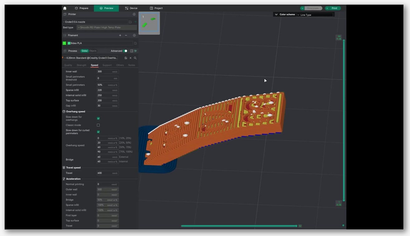
The four overhang-speed brackets (overhang_1_4 through overhang_4_4)
The Speed > Overhang Speed page is one of the most under-read pages in the OrcaSlicer wiki. The verbatim quote: “This is the speed for various overhang degrees. Overhang degrees are expressed as a percentage of line width.”
Four brackets, each named after how much of the line width has no material below it:
- Overhang speed 0-25% (internal variable
overhang_1_4_speed). Essentially still a wall, just barely overhanging. Usually safe to leave at wall speed. - Overhang speed 25-50% (
overhang_2_4_speed). Starts to need slowing. This is where you’ll feel the first improvement from a reduction. - Overhang speed 50-75% (
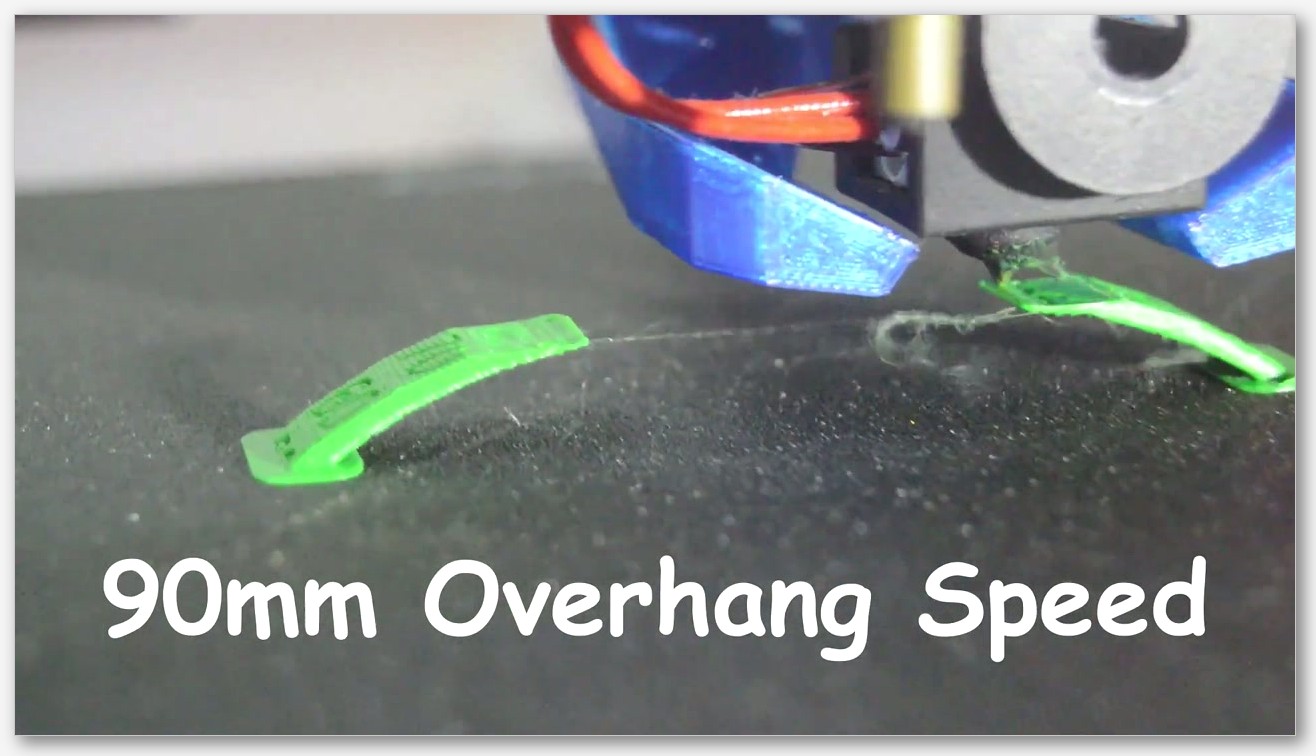
overhang_3_4_speed). Significantly unsupported. Plan to be well below wall speed here. - Overhang speed 75-100% (
overhang_4_4_speed). Effectively a bridge that the slicer is still treating as a wall. The slowest bracket, full fan if your filament allows it.
The wiki gives one critical piece of behavior that almost every YouTube tutorial gets wrong: “0 speed means no slowing down for the overhang degree range and wall speed is used.” Setting a bracket to 0 doesn’t mean “as slow as possible”. It means “ignore this bracket, use wall speed.” If you want the bracket to actually apply, give it a nonzero number. I’ve seen users set all four brackets to 0 thinking they were maximally slowing things down. They were doing the opposite.
Issue #7436 is worth knowing about: a user reported that setting one bracket value seemed to override the others. The thread is a useful read if you change a bracket and nothing else seems to honor it. Issue #4833 reports overhang speed simply not reducing as expected, and Issue #2646 documents a more recent interaction between the new curled-overhang detection and the overhang-speed system. None of these are guaranteed to apply to your version, but if your overhang speeds aren’t taking effect, search the issue tracker for your version first.
Make overhang printable (and the 45-60 degree rule)
This one’s a geometry modifier, not a speed setting. The wiki copy: “This setting will modify the geometry to print overhangs without support material.” It literally reshapes the model at slice time so that the steepest overhangs get a chamfer added in software. The companion field, “Make overhang printable – Maximum angle,” controls how aggressively. The wiki recommends: “Usually, a value between 45 and 60 degrees works well for most printers and models.”
The catch is that it changes the printed shape. If you’re slicing a functional part where the underside geometry matters, you don’t want this on. If you’re slicing a decorative print and just want the underside to not look like garbage, it’s a fast win.
There’s also “Make overhang printable – Hole area”, which controls how big a hole can be in the model’s base before the slicer fills it with conical material. Mostly relevant for parts with downward-facing holes that would otherwise need bridges across them. The quality settings wiki describes it as “Maximum area of a hole in the base of the model before it’s filled by conical material.”
Extra perimeters on overhangs, plus the “Reverse on even” trick
Two of the most underrated 2.x settings live in the Overhangs panel and most articles skip past them.
Extra perimeters on overhangs (internal variable extra_perimeters_on_overhangs). Wiki copy: “Create additional perimeter (overhang wall) paths over steep overhangs and areas where bridges cannot be anchored.” This adds a printed bracing wall along the inside edge of a steep overhang so the next line has something to sit on. It costs a small amount of print time and material. It can save a print that would otherwise sag, especially on the 50-75% bracket. I leave it on by default for any model with significant overhangs.
Reverse on even (overhang_reverse). Wiki copy: “Extrude perimeters in the reverse direction on even layers. This alternating pattern can drastically improve steep overhangs.” This is a slicer-side trick where every even layer’s perimeters extrude in the opposite direction from the layer below. The effect is that a freshly-extruded overhang line gets dragged backward against the previous layer instead of being pulled away from it, which dramatically reduces the upward curl that ruins steep overhangs.
The companion settings: Reverse internal only (overhang_reverse_internal_only), described in the wiki as “A simple way to reduce the texture on the outer wall is to only reverse the internal walls”, and Reverse threshold (overhang_reverse_threshold), which accepts a value in “0, mm, or %”. Internal-only is the right starting point if you don’t want the alternating-direction texture showing on your outer surface.
Slowdown for curled perimeters
This is its own setting, separate from the overhang-speed brackets, and it confuses people because the name sounds similar. slowdown_for_curled_perimeters targets a different defect: sharp corners and tips where the freshly-extruded line wants to curl upward as it cools, even when the segment isn’t technically classified as overhang. The two systems can both fire on the same wall.
If you see curl at corner tips but the underside of slopes looks fine, you want this enabled, not a lower overhang-speed bracket. Don’t confuse the two. I’ve watched users grind their 75-100% bracket down to 10mm/s trying to fix curl when the actual culprit was sharp-corner curl that the overhang system never even saw.
The OrcaSlicer bridging stack, every setting that matters
Now the spans. The Quality > Bridging panel is where you fix sagging, drooping, pebbly bridges. The wiki page is the authoritative reference for every label below.
Bridge flow ratio vs internal bridge flow ratio
Two separate settings, two separate jobs. Flow ratio (bridge_flow) controls external bridges, the ones that span open air between two anchor points. Internal bridge flow (internal_bridge_flow) controls bridges that the slicer auto-generates over sparse infill, the layer where solid top surfaces have to span the gaps in your infill pattern below.
The wiki gives one numeric recommendation: “Decrease this value slightly (for example 0.9) to reduce the amount of material for bridge, to improve sag.” That’s it. It does not state 1.0 as a default value in the wiki text, and I’m not going to invent one for you. The right way to use this is: if your external bridges sag, try 0.9 first. If they sag still, drop another 0.05. If they start looking pebbly or rough, you’ve gone too low.
Internal bridges (the ones over infill) often want a different ratio than external. The line below an internal bridge has actual material to bond to, just not solid material. External bridges have nothing. Treat them as separate calibrations. A common pattern: external around 0.9, internal closer to 0.95-1.0. Verify with a real test, not vibes.
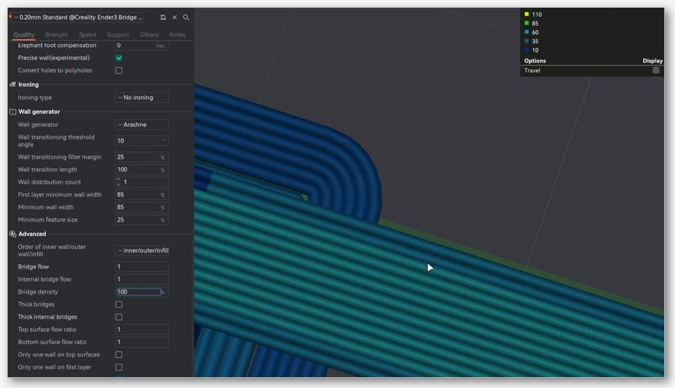
Bridge density, and the new 2.3.2-beta “above 100%” capability
Bridge density (bridge_density, with sibling internal_bridge_density) controls how tightly the bridge lines pack against each other. Wiki copy: “Decrease this value slightly (for example 0.9) to improve surface quality over sparse infill.” A lower density means more space between bridge lines, which sometimes paradoxically looks better because the lines don’t fight each other for space and the cooling has more time to set each one.
The interesting development arrived in 2.3.2-beta. From the release notes verbatim: “The maximum bridge density can now exceed 100%, allowing tighter spacing between bridge lines for better bonding and less sagging.” Before 2.3.2-beta, you couldn’t push density above 100%. Now you can, and it’s surprisingly effective on long external bridges where the lines tend to droop in the middle. The trade-off is that going too high pushes the lines into each other and produces a ridged, ugly underside. Try 105 to 110% before you go higher.
If you’re still on stable 2.3.0, you don’t have access to this. The 2.3.0 release notes don’t mention bridge-density changes at all. The >100% capability is specifically a 2.3.2-beta thing.
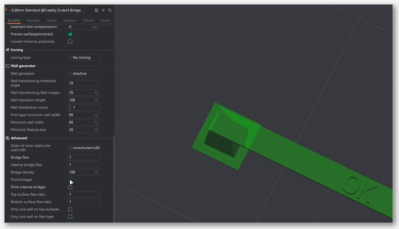
Thick bridges (and thick internal bridges)
Toggle: thick_bridges for external, thick_internal_bridges for internal. Wiki copy: “When enabled, thick bridges increase the reliability and strength of bridges, allowing you to span longer distances.” The slicer prints the bridge layer slightly taller than a normal layer, which gives more material to span the gap.
The trade-off, which the wiki acknowledges in the same section, is a rougher surface finish on the underside. Thick bridges are great for functional parts that span long gaps and need to actually hold load. They’re not great for decorative parts where you’ll see the underside. There’s no universal answer; it depends on whether you care more about reliability or finish.
Extra bridge layers
enable_extra_bridge_layer is a four-option dropdown: Disabled (the default), External bridge only, Internal bridge only, or Apply to all. What it does: prints an additional bridge layer on top of the first one, so the second layer has a fresh bridge surface to print onto instead of trying to print solid infill directly on the bridge lines.
When to use which:
- Disabled. Default. Fine for most prints with short, well-anchored bridges.
- External only. When external bridges look fine but the layer immediately above them looks rough. The extra layer smooths the transition.
- Internal only. Most useful one in my experience. Top surfaces over sparse infill come out cleaner because the second internal bridge layer fills the gaps the first one missed.
- Apply to all. Slower, more material, but the cleanest result for prints with lots of bridging. Worth trying on a model that’s been giving you grief.
Filter out small internal bridges
dont_filter_internal_bridges is a three-option dropdown: Filter (the default), Limited filtering, or No filtering. Despite the variable name, the UI label is “Filter out small internal bridges”, which makes sense once you stare at it long enough.
The slicer normally skips printing internal bridges over very small infill gaps because they often come out worse than just letting the next solid layer span them naturally. That’s the “Filter” default. If you’re seeing pinholes or rough patches on top surfaces over sparse infill, try “Limited filtering” first, then “No filtering” if that doesn’t help. No filtering means every detected internal bridge gets printed, which costs print time and can introduce its own artifacts.
Counterbore hole bridging, the dropdown nobody touches
counterbore_hole_bridging is a niche setting that solves a specific problem. Counterbore holes (think a stepped hole for a socket-head cap screw, where the head sits below the surface) create a horizontal disc of unsupported material at the bottom of the wider section. Without help, that disc tries to bridge across a circular gap, which usually fails.
The three options:
- None. Slicer treats it like any other bridge. Usually fails on larger holes.
- Partially Bridged. Slicer adds an extra bridging strategy that gets some material across without trying to fully bridge the disc. Cleaner result, still leaves a small hole.
- Sacrificial Layer. Slicer adds a sacrificial layer of material across the counterbore that you snap out after the print. Strongest result, most post-processing.
If you print a lot of functional parts with counterbore holes, this is one of the better dropdowns in OrcaSlicer. Most users never touch it because they don’t realize it’s there.
Cooling, the half of “overhang fix” that lives in the Material tab
Here’s the part that traps people. You can perfect your Quality tab and Speed tab settings, and if the cooling in the Material tab is wrong, your overhangs will still sag. Cooling is half the fight. The good news is OrcaSlicer’s cooling logic for overhangs and bridges is more granular than people realize.
“Force cooling for overhangs and bridges”, the override that beats your filament profile
This is a switch on the material cooling tab. When it’s on, the fan ramps to your overhang/bridge fan setting regardless of your filament profile’s normal fan curve. When it’s off, the filament profile wins.
Most of the time you want this on. The exception is PETG. PETG benefits less from aggressive cooling on overhangs because its layer adhesion suffers more than its overhang quality improves. If you’re printing PETG and your overhangs are technically passable but your layer adhesion is garbage, try turning this off and seeing if you can live with slightly worse overhang quality in exchange for parts that don’t crack along layer lines.
“Overhang cooling activation threshold”, read the label carefully
This one is the single biggest source of confusion in the cooling tab. The threshold is expressed as a percentage of line width unsupported, not as an angle. Same logic as the four overhang-speed brackets. If you set the threshold to 50%, the dedicated overhang fan speed kicks in once a wall segment has 50% of its line width hanging out over nothing.
Most generic articles describe this as “the angle at which overhang cooling kicks in.” That description is wrong, and it’ll lead you to set values that don’t behave the way you expect. Read the wiki page; it’s explicit on this point.
There’s an older issue, #5861, where a user reported that threshold values from 10 to 95% all behaved identically on an older 2.x version. I don’t have a clean reproduction on 2.3.x and I’m not going to claim it’s still a current bug. If your threshold tweaks aren’t doing anything visible, search the issue tracker for your version before assuming you’ve misconfigured something.
“Overhangs and external bridges fan speed” vs “Internal bridges fan speed”
This is one of OrcaSlicer’s quietly excellent features and most articles miss it entirely. The slicer exposes two separate fan speeds: one for overhangs and external bridges, and a different one for internal bridges. Both are in the Material > Cooling tab.
External bridges and overhangs are the same case: you almost always want maximum cooling because the freshly-extruded plastic has nothing under it to conduct heat away. Internal bridges are different: they’re sitting on top of sparse infill, which conducts some heat away, so you can usually get away with less fan. Less fan means better layer adhesion in the layers above, which means stronger parts.
A common setup that works: overhangs and external bridges fan at 100%, internal bridges fan at 60-70%. The exact numbers depend on filament. The point is they should be different values, not the same value.
For reference, the full list of fan-related labels in OrcaSlicer’s cooling tab, verbatim from the wiki: “No cooling for the first” layers, “Full fan speed at layer”, “Min fan speed threshold”, “Max fan speed threshold”, “Keep fan always on”, “Slow printing down for better layer cooling”, “Don’t slow down outer walls”, “Min print speed”, “Force cooling for overhangs and bridges”, “Overhang cooling activation threshold”, “Overhangs and external bridges fan speed”, “Internal bridges fan speed”, “Support interface fan speed”, “Ironing fan speed”, and “Auxiliary part cooling fan”. That’s a lot of granularity. Most users see “Fan speed” and stop reading.
The fan-cycling problem on stacked bridge/overhang sequences
Discussion #8808 in the OrcaSlicer repo, opened by user Blop32, documents a real-world annoyance: on parts with a lot of short bridge or overhang segments back-to-back, the fan can oscillate up and down in rapid succession. Up to overhang fan speed, back down to part fan speed, up again, down again. You can hear it, and the inconsistent cooling produces visible banding on the layers above.
The workaround the reporter found, which I’ve used myself and which works on the parts I’ve tried, is to set “Smoothing Segment Length” in the advanced Speed settings to a value like 3. That tells the slicer to smooth speed changes over a longer path length, which incidentally also smooths the fan-curve transitions. It doesn’t solve the problem at the firmware level but it’s a real improvement.
I haven’t seen a maintainer response in the thread that confirms this as an official workaround. Treat it as community knowledge.
Calibration, running OrcaSlicer’s built-in bridge flow test
Before you go tweaking individual bridge settings, run OrcaSlicer’s built-in bridge flow calibration. It exists for a reason and it’s quick.
The Calibration menu lives under the top-right of the main OrcaSlicer window. You’ll see entries for Pressure Advance, Flow Rate, Temperature Tower, and Bridge Flow (among others). Click Bridge Flow. The slicer generates a test print with multiple bridge spans at different flow ratios. You print it, look at which row has the cleanest underside, and update your filament profile to that flow ratio.
There’s also a community test model on Printables, 3D Printing Bridge Calibration Test (Basic & Advanced) by Iker Libano / KNIN Custom, that’s worth printing in addition to OrcaSlicer’s built-in one. It has longer spans and a wider range of test conditions than the slicer’s quick test.
Reading the test print
What you’re looking for, in priority order:
- No droop in the middle of the span. If the test row in the middle of your range is flat across the span, that flow ratio is in the ballpark. Drooping rows are too low flow.
- No pebbly or blobby texture. If the underside looks like cottage cheese, flow is too high.
- Clean parallel lines. The bridge lines should sit next to each other without overlapping into ridges and without gapping into stripes of empty space.
- No upward curl at the edges. If the bridge curled up at the anchor points, your fan ramp wasn’t ready in time. That’s a cooling fix, not a flow fix.
Pick the row that satisfies all four. If no row satisfies all four, run the test again with a different speed value to widen the range.
What to do if the calibration test passes but real prints still sag
Happens often. Calibration prints have short, clean spans on a flat plate. Real models have longer spans, weirder geometry, and stacked bridges over overhangs over more bridges. If your calibration is clean and your real prints still sag, work through these in order:
- Cooling. The calibration test ran with the slicer’s default cooling logic, which may not match what your real model triggers. Verify the overhang fan setting is actually firing where you think it is by looking at the preview’s fan-speed visualization.
- Internal vs external mismatch. If the real-model sag is on top surfaces (over infill), that’s an internal bridge problem, and the external bridge flow calibration didn’t test that path. Calibrate internal bridge flow separately.
- Model geometry. A long unanchored span that exceeds the test print’s span length will sag even at perfect flow ratio. There’s a physical limit. Tree supports or geometry changes solve this, not slicer settings.
- Filament moisture. Wet filament bubbles and pops during extrusion, which destroys bridge consistency no matter what flow ratio you set. Dry your spool. Temperature tower tests can hint at moisture issues if every temperature looks bad.
Printer-class tuning matrix
Different machines have different strengths and limits. The same overhang settings that nail it on a Bambu X1C will produce mush on a stock Ender 3 because the part fan can’t move enough air. Here’s a starting matrix. These are starting points, not official defaults. Run the calibration test for your actual machine and filament before trusting any number in this table.
| Printer class | External bridge flow starting point | Overhang 75-100% speed direction | Fan strategy | Known quirk |
|---|---|---|---|---|
| Bambu X1C / P1S / A1 | 0.9-0.95 | Slow, around 30-50% of wall speed | Full part fan, aux fan if available | Aux fan on X1C can over-cool, dial back for PETG |
| Voron 2.4 / Trident | 0.85-0.9 | Slower, hot chamber limits cooling | Cooling-limited, lower fan | Hot chamber for ABS means overhangs are harder than on open frames |
| Ender 3 V3 SE / Neo / Ender 5 | 0.9 | Significantly slower, often 20-40% of wall | Stock fan is underpowered, run at 100% | Stock part fan is the weak link, mod it before fighting settings |
| Prusa Core One | 0.9 | Moderate slowdown | Strong active cooling | Community OrcaSlicer profiles still maturing in 2026, double-check |
| Sovol SV06 / SV08 | 0.9-0.95 | SV08 needs more aggressive slowdown than its wall speed implies | SV08 has strong active fan | Don’t carry over wall speeds into overhang brackets unchanged, SV08 wall speeds are high |
| QIDI X-Max 3 / Q1 Pro | 0.85-0.9 | Slower, chamber-heated | Cooling-limited like Voron | Heated chamber actively works against overhang cooling, lower bridge flow more than open-frame |
Bambu (X1C, P1S, A1)
Bambu’s part cooling is strong out of the box. The X1C in particular has an aux fan that can over-cool on materials that don’t want it, and the overhang fan setting can compound the issue. Bias toward slower overhang speeds (the 75-100% bracket significantly below wall speed) and full part fan. On PETG specifically, dial the overhang fan back to 70-80% and turn off “Force cooling for overhangs and bridges” to keep layer adhesion intact.
Voron (2.4, Trident)
Vorons run a hot chamber for ABS, ASA, and other high-temperature materials. Hot chamber means less of a temperature gradient between the newly-extruded line and the surrounding air, which means slower cooling, which means overhangs are harder. Drop bridge flow more aggressively (0.85 is a reasonable starting point) and slow down the high overhang brackets further than you would on an open-frame printer. Internal bridges are usually fine because the chamber heat doesn’t fight the cooling there as hard.
Ender (3 V3 SE, Neo, Ender 5)
Stock Ender part fans are the weak link. You can run them at 100% and they still move less air than a Bambu at 50%. If your overhangs are bad on a stock Ender and you’ve already maxed the fan, the fix is hardware (a better fan, a Satsana or similar duct) rather than slicer settings. Slicer-side, lean on the overhang-speed brackets harder than on a better-cooled machine. The 50-75% bracket might need to be 25-35% of wall speed instead of the 60-70% you’d run on a Bambu.
Prusa Core One
The Core One is new (2025) and the OrcaSlicer community profile situation is still being worked out. If you’re running a community profile, check when it was last updated and against what OrcaSlicer version. The Core One’s active cooling is strong, so overhangs should be tractable, but I’d run the bridge flow calibration on your specific filament before trusting any community profile’s bridge settings.
Sovol (SV06, SV08)
The SV08 is interesting because its wall speeds out of the box are high enough that even the 0-25% overhang bracket can struggle if you leave it at wall speed. The fix is to actively set lower numbers in the lower brackets even when you wouldn’t bother on a slower machine. The SV06 is more conventional and the standard Ender-class advice mostly applies.
QIDI (X-Max 3, Q1 Pro)
Enclosed-chamber machines, similar story to Voron. The heated chamber actively works against overhang cooling. Drop bridge flow toward 0.85, slow down all the upper overhang brackets, and accept that overhangs on these machines will never be as crisp as on an open Bambu. The trade-off is real: chamber heat for warping-resistant high-temperature prints, at the cost of overhang quality.
Filament-by-filament adjustments
Filament is the other half of the equation. Two machines on the same OrcaSlicer profile, one running PLA and one running PETG, will produce wildly different overhang quality with identical slicer settings. Here’s how I adjust per material.
PLA
The easy case. PLA loves fan, sets up fast, and forgives most slicer settings. Run external bridge flow at 0.9, full fan on overhangs and external bridges, lower internal bridge fan around 60-70%. The 75-100% overhang bracket can run at 30-50% of wall speed and look good. PLA is the calibration baseline.
PETG
The hard case. PETG hates aggressive cooling, which is exactly what overhangs need. The trade-off you’re managing is: more fan means better overhangs and worse layer adhesion, less fan means stronger parts and worse overhangs. There’s no setting that gives you both.
My PETG starting point: external bridge flow 0.95 (PETG is more forgiving on flow than PLA because it’s stickier when fresh), overhang fan at 70-80% not 100%, “Force cooling for overhangs and bridges” off unless overhang quality is non-negotiable. Watch for the fan-cycling problem in discussion #8808 specifically on PETG, since the layer-adhesion cost of those cycles is worse on PETG than on PLA.
ABS / ASA
Enclosed-printer territory. Chamber heat means less cooling effectiveness, so external bridges and overhangs are harder to get clean. Drop bridge flow toward 0.85, accept slower overhang speeds, and consider whether the part actually needs visible-quality undersides or if a slightly rougher overhang is fine for a functional part. ABS-ASA functional parts often don’t need pretty undersides.
TPU
Bridging on TPU is rough. The flexible material wants to drape and stretch instead of supporting itself. Try external bridge flow at 1.0 (yes, higher than PLA, because TPU lays down less rigidly) and crank the fan. Honestly, on long bridges I just add supports. TPU is the one filament where I lean on the model side more than the slicer side.
PA (Nylon)
Hygroscopic, sensitive to chamber temperature, generally a nightmare for overhangs. Dry your spool aggressively. Run a temperature tower first to make sure your temperature isn’t part of the problem. Bridge flow around 0.9 to 0.95. Don’t expect Bambu-level overhang quality. PA functional parts almost always get supports for any overhang past 45 degrees.
Common mistakes to avoid
The anti-pattern list. Every one of these traces back to either a wiki point I’ve already cited or a community thread.
- Setting overhang speed brackets to 0 thinking that means “as slow as possible”. It doesn’t. From the wiki: “0 speed means no slowing down for the overhang degree range and wall speed is used.” Zero means “skip this bracket”. Use real numbers.
- Treating “Overhang cooling activation threshold” as an angle. It’s a percentage of line width unsupported. Same as the four overhang-speed brackets. The wiki is explicit. Most user-facing articles online get this wrong.
- Using one fan speed for both overhangs and internal bridges. OrcaSlicer separates them. Use both. Overhangs and external bridges at high fan, internal bridges lower.
- Tuning bridge flow without calibrating first. The wiki gives 0.9 as an example, not a default. Run the calibration test and use the result for your filament.
- Assuming 2.3.0 has the >100% bridge density capability. It doesn’t. That’s a 2.3.2-beta release-note item. If you’re on stable 2.3.0, you can’t push density above 100% even in the UI.
- Confusing “Slowdown for curled perimeters” with the four overhang-speed brackets. They target different defects: curl at sharp corners vs sag on slopes. Set both, but for different reasons.
- Disabling “Detect overhang wall” without realizing it. Imported profiles from older slicers sometimes ship this off. If your overhang speeds aren’t applying, check this first.
- Cranking fan to 100% on PETG and wondering why parts crack. PETG overhangs and PETG layer adhesion are in direct conflict. You can’t fully optimize both. Pick what the part needs.
When the slicer can’t save you, model-side fixes
Sometimes the slicer can’t fix it. The geometry is asking for something that physics won’t deliver. Here’s the escape hatch.
Chamfer the overhang in CAD. A 45-degree overhang almost always prints cleanly. A 60-degree overhang sometimes does. A 70-degree overhang almost never does, regardless of how good your slicer settings are. If you control the CAD, add a chamfer or fillet that brings the angle below 60. Cheaper than tuning.
Add a sacrificial wall. If you can’t change the geometry, you can sometimes add a thin sacrificial wall outside the part that gives the overhang something to lean against. Snip it off after the print. Ugly, effective.
Tree supports. OrcaSlicer’s tree support implementation is good. If you’ve been resisting supports because of how aggressive the older PrusaSlicer “auto support” used to be, give the modern tree support algorithm another look. Tree supports generate less material, peel off cleanly, and rarely scar the part. For overhangs above 60 degrees they’re almost always the right call.
Counterbore the hole instead of bridging it. If your geometry has a horizontal disc of unsupported material, the counterbore-hole-bridging setting we covered earlier might cleanly solve what no amount of bridge tuning will.
Split the part. Sometimes the best slicer setting is “print it as two parts and glue them.” A part with a difficult overhang can often be sliced into two halves that each print without overhangs, then bonded. Functional parts rarely need to be one piece.
Recalibration cadence
You don’t calibrate bridge flow once and forget about it. The values drift with filament batch, with nozzle wear, with ambient humidity, with seasonal temperature shifts. Here’s when I rerun:
- New filament spool, even same brand. Different batches measure differently. Run the bridge flow test, takes 15 minutes.
- New filament brand or material. Always. Don’t skip.
- Nozzle swap. Different nozzle diameters need different bridge speeds and flow ratios. Different materials (steel vs hardened steel vs ruby) can also change flow behavior subtly.
- Big ambient temperature swing. Summer humid garage vs winter dry garage. The filament behaves differently. Rerun if your prints start drifting.
- OrcaSlicer version update. Less often, but possible. The 2.3.2-beta bridge-density change is a good example: if you take the update, you have a new tool to test with.
For a fuller schedule of which tests to rerun when, see the OrcaSlicer recalibration schedule. The short version: bridge flow gets rerun on every filament change, cooling settings get a sanity check on every season change.
OrcaSlicer ships with one of the most granular overhang and bridging stacks of any FDM slicer in 2026. The price of that granularity is that you have to know the labels and the order to touch them in. Diagnose the defect first, work the right tab second, and run the calibration test before you start guessing numbers. Most “OrcaSlicer overhangs and bridging problems” turn out to be one tab away from a fix the user already had the tools for.
If you’re starting fresh and need the latest build, grab it from the official OrcaSlicer GitHub releases page. 2.3.2-beta is where the new bridge density capability lives if you want to play with that today; 2.3.0 stable is the safer pick if you don’t want beta surprises mid-project.
Related OrcaSlicer guides
- OrcaSlicer Troubleshooting: Master Index of Every Common Fix
- OrcaSlicer Settings Not Saving: Diagnose the Profile Reset Bug
- OrcaSlicer Can’t Connect to OctoPrint: Every Fix That Works
- OrcaSlicer Stringing & Oozing Fixes: Ranked by Impact (2026)
- OrcaSlicer Max Volumetric Speed Test: Find Your Hot End Limit (2026)