
I lost an entire Saturday to pressure advance once. I had a brand new spool of matte PLA, a freshly tuned Voron, and a Benchy that kept printing with corner bulges so fat you could see the seam from across the room. So I opened the OrcaSlicer Calibration menu and stared at three options that all claimed to fix the same problem: PA Line, PA Pattern, PA Tower. Three tests. One bug. I picked PA Line first because it was at the top of the list, ran it, eyeballed the result, saved a value, reprinted the Benchy, and got the exact same bulges. Different number, same bulges.
It turned out I’d been reading the test wrong, running it on a printer whose firmware couldn’t act on the value, and then forgetting that OrcaSlicer doesn’t actually save your calibration result back into the filament profile. Nothing about that experience was obvious from the menu. So I’m writing the article I wish I’d had: the honest comparison of OrcaSlicer’s three pressure-advance tests, which one to use for which printer, how to read each one without falling into the “pointiest corner” trap, and what to do when the test refuses to slice.
I’ll also clear up the cooling-tower question, because that’s a search query I see a lot. Short version: OrcaSlicer doesn’t ship one. The longer version comes later. For now, if you came here to choose between PA Line, PA Pattern, and PA Tower, keep reading.
TL;DR decision matrix
If you skim only one section, make it this one. The three tests are not interchangeable, and picking the wrong one wastes filament. I’ve boiled down the upstream wiki, the Ellis Print Tuning Guide, and a stack of GitHub issues into a single table.
| Test | Best for | Avoid if | Firmware | Time to print |
|---|---|---|---|---|
| PA Line | Quick first-pass scan, any printer | Your first layer is unreliable | Klipper, Marlin (with Linear Advance), Bambu, RepRap | Under 5 min |
| PA Pattern | Fine-grained, most accurate reading | Marlin without LA compiled in, nozzle larger than 0.4 mm, layer height above 0.24 mm | Klipper (validated). Marlin and Bambu are experimental per the Adaptive PA wiki. | Under 10 min |
| PA Tower | First layer is shaky, you trust calipers more than your eyes | You want sub-0.005 PA resolution | Klipper, Marlin Linear Advance | 15 to 25 min |
The quick decision tree: if you’re on Klipper with input shaper already calibrated, run PA Pattern. If you’re on a stock Bambu X1C or P1S, run PA Line and skip the Flow Calibration toggle. If your first layer is shaky and you don’t want to fight it before every test, run PA Tower. If you’re on Marlin and you haven’t compiled Linear Advance into your firmware, none of these tests will do anything because the printer can’t act on the value. I’ll come back to that one.
If you only have time to do one calibration pass today and you’re not sure where to start, do PA Line. It runs in under five minutes, it works on every firmware Orca supports, and it’ll get you 80 percent of the way to a clean corner. PA Pattern is the precision pass you do after you’ve nailed flow ratio and run a temp tower for your filament.
The cooling-tower question: does OrcaSlicer have one?
I’m putting this here because the question gets asked enough that ignoring it would be dishonest. OrcaSlicer does not ship a cooling tower or fan-speed-tower calibration test. The Calibration menu has nine entries and none of them is a part-cooling test. The full list is Temperature, Volumetric Speed, Pressure Advance, Flow Ratio, Retraction, Tolerance, Cornering, Input Shaping, and VFA. The official wiki confirms this on the Calibration page.
There’s an open feature request on GitHub asking for one. Discussion #2906, “possibility to do fan speed tower test,” is the canonical thread. As of writing, it’s still a community request rather than a shipped feature. Issue #919 covered the same ground back in May 2023 and went stale. So if you searched for “cooling tower” and landed here expecting a one-click test, that’s why you couldn’t find it.
If you actually want to dial in part-cooling, the community workflow is to print a fan-speed STL like the caste1200 Ultimate Fan Speed Test from Printables and step M106 S<value> commands in the printer’s layer-change G-code at fixed Z bands. It’s a manual workflow, not a slicer feature. For most use cases, tuning the filament profile’s overhang_fan_speed, overhang_fan_threshold, full_fan_speed_layer, and close_fan_the_first_x_layers keys gets you most of the way without printing a tower at all.
Now, the reason this matters in a pressure advance article is that the symptoms overlap. Bulged corners can be a PA problem or a cooling problem. Droopy overhangs are a cooling problem. Bulged corners on every wall, regardless of whether they’re overhanging, are a PA problem. If you fire up PA Line and every single line looks rough, the issue is probably upstream of pressure advance. Run a temp tower first, check your flow rate, and then come back to pressure advance.
What PA Pattern actually is
Menu path: Calibration, then Pressure Advance, then Pattern Method. That’s three clicks. What you get is a hand-written 2D pattern test adapted from Andrew Ellis’ pattern method generator, which was itself derived from the Marlin pattern method developed by Sineos. OrcaSlicer’s Pressure Advance calibration wiki documents the lineage, and Obico’s comprehensive guide says the same thing in plain English.
Mechanically, here’s what the slicer is doing. It generates a thin rectangular prism that acts as a frame. Inside that frame, it writes a custom G-code pattern of straight lines with sharp acceleration and deceleration corners. Each row of the pattern is printed at a different pressure advance value, and the value is labeled in extrusion next to the row. The “infill” is not real slicer infill. It’s hand-written G-code embedded into the layer instructions of the prism. That detail matters because it explains why the test breaks if you change layer height or nozzle size: the G-code generator wasn’t designed for those configurations.
When you open the Pattern Method dialog, you’ll see a configuration window with start PA, end PA, step PA, and a couple of presets. Bowden defaults use a wider range, 0.02 to 1.0, because Bowden setups need a much higher PA value to compensate for the PTFE compliance. Direct drive defaults sit in the 0.0 to 0.1 range with a step of 0.002. Pick the preset that matches your hardware. If you’re on a Voron Mini Stealthburner, that’s direct drive. If you’re on an Ender 3 with the stock Bowden setup, that’s Bowden.
One configuration trap worth flagging now: if you’re on a Bambu X1C or P1S, do not tick the Flow Calibration box during PA Pattern. Bambu firmware handles flow calibration separately and the two tests interact in ways that make the pattern unreadable. I’ve seen this trip up a lot of new Bambu owners. Run flow rate as its own test, in its own calibration pass.
Total print time on PA Pattern is under ten minutes for most configurations. It’s the test I run when I want a precise reading and I have a working first layer. Speaking of which.
PA Line vs PA Pattern vs PA Tower
Now we get into the real comparison. I’ll go test by test, then summarize.
PA Line
PA Line is the fastest and simplest of the three. OrcaSlicer prints a series of straight extrusion lines on the bed, each at a slightly different pressure advance value, with the value labeled next to the line. The whole test is one layer tall. It runs in under five minutes and uses almost no filament.
You read it by looking at where each line starts and ends. The correct line is the one where the start of the line doesn’t show a bulge from over-extrusion and the end doesn’t show a taper or a dropped blob from under-extrusion. The width should stay consistent end to end. Pick the line with the cleanest transitions, not the line that “looks best overall.” That’s a distinction I’ll come back to in the reading section.
PA Line is the universal fallback. It works on Klipper, on Marlin with Linear Advance compiled in, on Bambu firmware, and on RepRap firmware. The Obico guide describes it as inspired by the K-factor calibration pattern, which is true: it’s the simplest possible expression of the same idea. If you run only one PA test in your life, this is the one to run.
Its main weakness is that it lives entirely on the first layer. If your first layer is over-extruded, under-extruded, or tilted because of a bad bed mesh, the test is wrong. Garbage in, garbage out. I always run a quick first-layer test (the Orca Calibration menu has one called “First Layer” or you can use the Voron purge line) before I trust any PA Line result.
PA Pattern
PA Pattern is the precision pass. It prints the rectangular prism I described above with rows of hand-written 2D segments, each row at a different PA value, sharp corners on every segment so you can see where the pressure changes are smoothest.
It’s more accurate than PA Line because the sharp corners exaggerate the pressure advance error: at a corner, the extruder has to suddenly slow down and the molten filament has to suddenly stop being pushed forward. If your PA value is too low, the corner bulges because the pressure keeps building. If your PA value is too high, the corner shows a gap because the firmware retracts pressure too aggressively. You can spot a 0.005 difference in PA on the pattern that you’d miss on PA Line.
The firmware support story is where you have to be careful. The Ellis upstream pattern method is documented as compatible with Klipper, Marlin, and RepRapFirmware. OrcaSlicer’s specific implementation, on the other hand, is validated mostly on Klipper. The Adaptive Pressure Advance wiki says it directly: the feature was tested with Klipper-based printers, and while it may work with Marlin or Bambu Lab printers, it’s currently untested with them.
In practice, what this means: if you’re on a Voron, a stock Klipper Ender, a Vzbot, or anything Klipper-flashed, PA Pattern works as documented. If you’re on a stock Bambu, the test will run and the print will look fine but the results aren’t validated by the upstream maintainers. If you’re on Marlin and you haven’t compiled Linear Advance into the firmware, the firmware just ignores the M900 K commands the slicer sends, and every row of the pattern looks identical. The print isn’t broken. The firmware silently dropped the calibration data.
One more Klipper-specific caveat: PA Pattern is most accurate when input shaper is already calibrated. Ellis is explicit about this in the pattern method article: do not attempt to calibrate adaptive PA for an acceleration that is larger than what the Klipper input shaper calibration tool recommends. At high accelerations, the shaper smooths corner geometry and you’ll misread the pattern. Run a resonance compensation pass first.
PA Tower
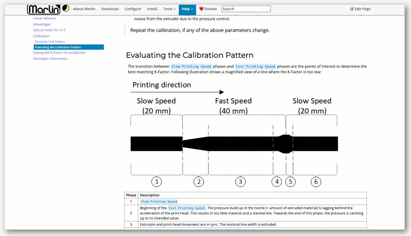
PA Tower is the K-factor legacy method, adapted from Klipper’s TUNING_TOWER macro. The slicer prints a tall hollow square tower and steps the pressure advance value as Z height increases. You print the tower, find the height where the corners look cleanest, measure that height with calipers, and back-calculate the PA value.
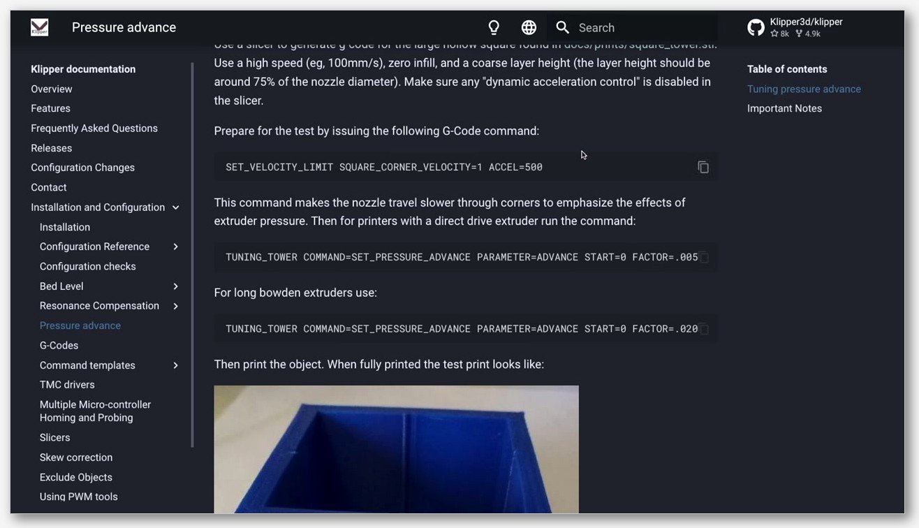
The math is simple. For a direct drive extruder, PA equals (measured height in mm times 0.002) plus start_PA. For a Bowden setup, PA equals (measured height times 0.02) plus start_PA. So if you ran a tower with start_PA = 0 and factor = 0.005 and the cleanest band sits 4.7 mm up, your PA value is 0 + 4.7 times 0.005, which is 0.0235. I’ve seen that exact example in the Klipper docs, and it lines up with what OrcaSlicer produces.
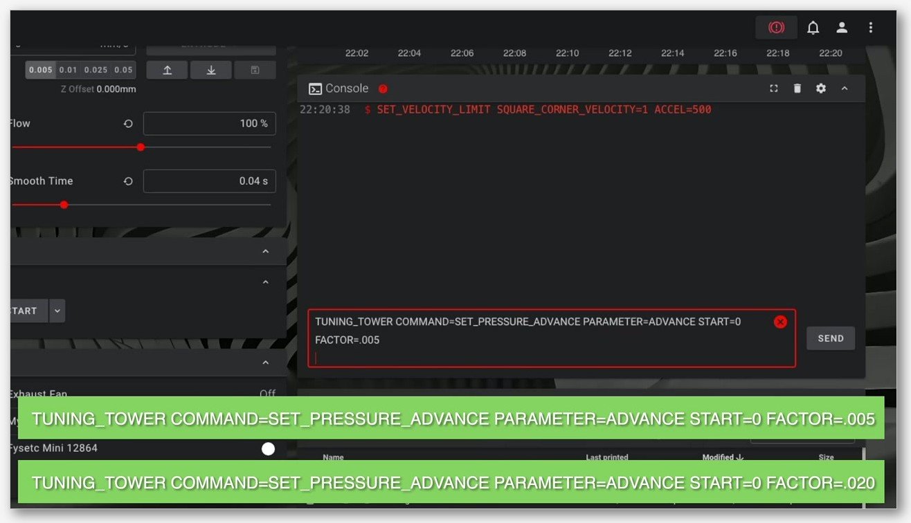
PA Tower’s advantage is that it’s less sensitive to first-layer quality. Most of the test happens up in the air, so a wonky first layer doesn’t ruin the read. Its disadvantage is that the resolution depends on the factor and the tower height. With a 0.005 factor and a 20 mm tower, you can resolve PA changes down to about 0.001, which is fine for most filaments. If you need finer resolution than that, switch to PA Pattern.
PA Tower’s firmware support is similar to PA Pattern: validated on Klipper, works on Marlin with Linear Advance, partial support on Bambu firmware. The Klipper docs recommend printing the tower above 120 mm/s so the pressure effects are pronounced enough to read. Don’t run it at 50 mm/s and expect to see the bands clearly.
Quick recap
PA Line: fast, universal, dependent on first layer. PA Pattern: precise, Klipper-validated, breaks on big nozzles. PA Tower: forgiving of first layer, requires calipers, K-factor lineage. Pick one, read the section below on how to read it, save the value, move on with your life.
How to read each test (it is not the pointy corner)
This is where I lost most of my Saturday. The classic mistake is to read PA Pattern by looking for the row with the sharpest, most knife-edge corner and declaring that the right answer. That’s wrong, and it’s wrong in a specific way that the Ellis guide warns about.
Reading PA Pattern correctly
The thing you’re looking for is the row where the line width stays even across the entire segment, including through the corner. Not the row with the pointiest corner. Ellis writes it as: “you are looking for the sharpest corner with the fewest artifacts (gaps, bulges, divots).” The Creality community forum has a clearer rephrasing of the same idea: “it can never be pointy because of the nozzle pattern which is a circle. The goal is to have same width throughout the line so that the final shape won’t affect the dimensions of the object.”
Translation: your nozzle is round. The corner that the nozzle traces will always have a small radius equal to the nozzle’s deposition profile, no matter how perfectly you tune PA. If you keep cranking the PA value looking for a literal point, you’ll overshoot and start under-extruding the segments. The correct read is the row where the line width is constant from end to end. The corner will still have a small radius. That’s fine. That’s physics.
Practical tip: hold the print up to a light at a low angle. Even line width shows as a uniform shadow. Bulging or gapping shows as a varying shadow. Train your eye on the shadow rather than the geometry. After a few prints you’ll see it instantly.
Reading PA Line correctly
PA Line is read with no calipers, just your eyes. Look at the labeled lines on the bed. The correct line is the one where the start doesn’t bulge from over-pressure, the end doesn’t taper from under-pressure, and the width stays uniform end to end. Pick the line with the cleanest start and end transitions.
The most common mistake on PA Line is picking the line that “looks best overall.” Overall aesthetic is not the metric. The metric is the start-to-end behavior. A line can look prettier overall because of where it sits on your bed (better cooling, better bed adhesion) but still have a worse PA value than a line two rows over. Focus on the transitions.
Reading PA Tower correctly
PA Tower is the one test where I’d recommend calipers. Pick the Z height where the printed corners look cleanest, measure that height from the build plate, and plug it into the formula. For direct drive: PA = (Z in mm * 0.002) + start_PA. For Bowden: PA = (Z in mm * 0.02) + start_PA.
If your start_PA was zero (which is the default for direct drive) and your cleanest band is at 12 mm, your PA value is 0.024. Save that number. Don’t try to be clever and bisect between two bands: PA Tower’s resolution doesn’t really go below about 0.001 anyway.
Saving the value manually
This is the step that tripped me up on my first Saturday. OrcaSlicer’s PA calibration tests do not auto-save the chosen value back to the filament profile. The test prints. You read the result. You then have to manually paste the number into the filament profile, or all your work was for nothing.
I’ve seen this confusion in half a dozen Reddit threads and forum posts. People run PA Pattern, decide on a value, close the test, slice their actual model, print it, and get the exact same corner artifacts they started with. Because OrcaSlicer’s calibration tests are essentially throwaway print jobs. They don’t write anything back to your filament profile when they finish. You have to do that manually.
The exact path is:
- Decide on your value from the test print (let’s say 0.044).
- Open the Filament settings dialog by clicking the pencil or edit icon next to the active filament profile in the main UI.
- In the Filament settings dialog, look for “Enable pressure advance” in the Basic information section. Tick the checkbox.
- In the “Pressure advance” field next to it, enter your value.
- Save. If you started from a system profile, you’ll typically want to “Save as” a custom profile so future Orca updates don’t overwrite your value.
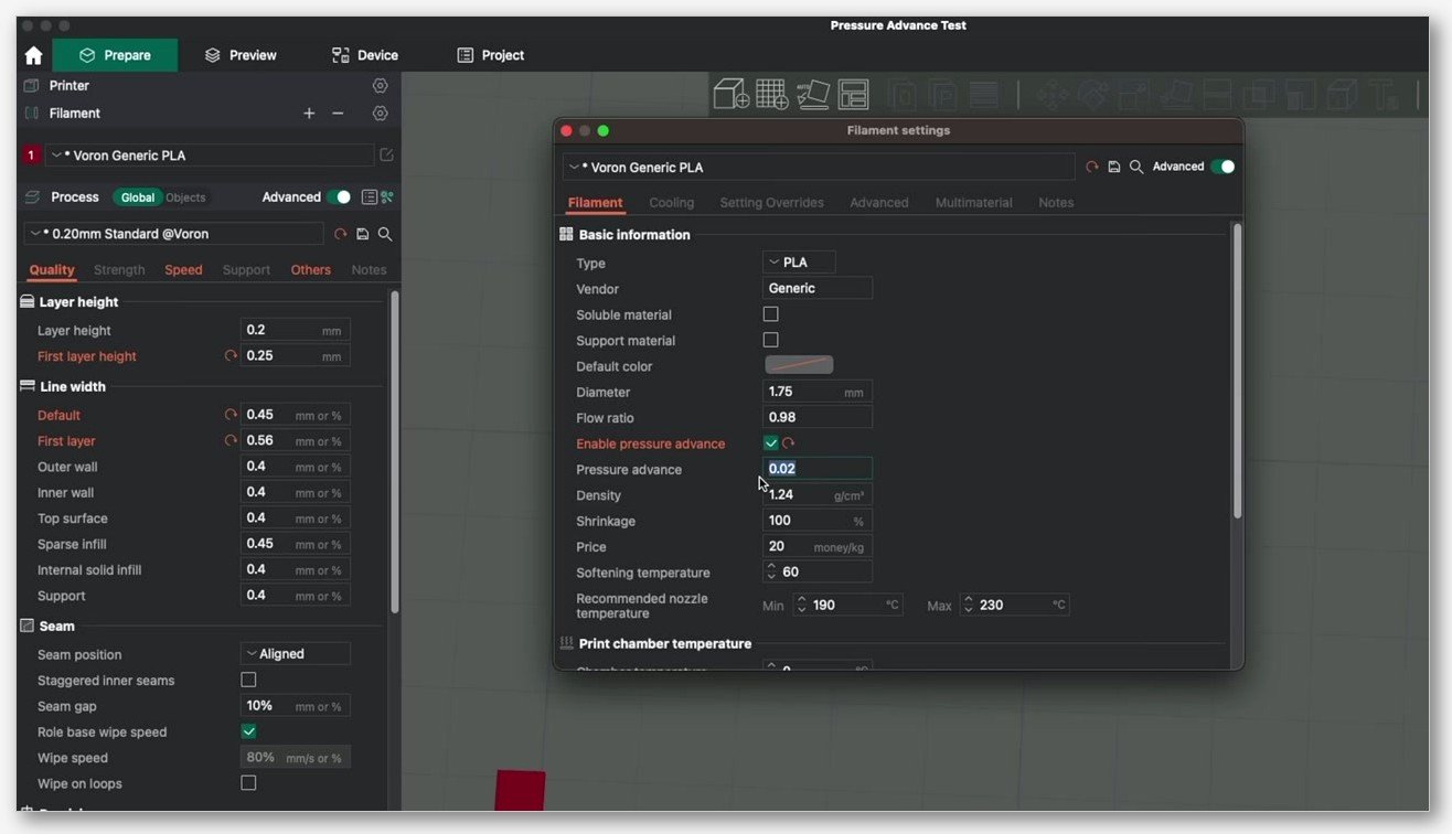
The underlying filament key OrcaSlicer writes is pressure_advance, gated by enable_pressure_advance. You can confirm this by exporting your filament profile to JSON and grepping for those keys. The Material Flow Ratio and Pressure Advance wiki documents the same field.
On the printer side, once the value is saved, OrcaSlicer emits the firmware-appropriate command at the start of the print. For Klipper that’s SET_PRESSURE_ADVANCE ADVANCE=<value>, applied per filament. For Marlin Linear Advance, that’s M900 K<value>. For Bambu firmware, the value is wrapped in the proprietary G-code shim Bambu uses. You don’t need to think about any of this once it’s saved. You just need to actually save it.
Ten common mistakes that ruin a PA calibration
I’ve made eight of these. The other two I’ve watched friends make. None of them are obvious from the OrcaSlicer UI.
- Running PA Pattern on Marlin without Linear Advance compiled in. The G-code runs, the print looks fine, and the firmware silently ignores every PA change. Every row looks identical. The first time this happened to me I thought my hotend was clogged. Check that your Marlin build has
#define LIN_ADVANCEenabled. If it doesn’t, none of these tests are meaningful for you. - Running PA Pattern on Klipper without input shaper calibrated. At the high accelerations the pattern uses, an uncalibrated shaper smooths corner geometry and you misread the result. Calibrate input shaper first. It’s a one-time setup per printer, and it makes every subsequent calibration more accurate.
- Confusing PA calibration with cooling fan calibration. Corner artifacts on overhangs are usually cooling. Corner artifacts on flat walls, regardless of overhang, are usually PA. If every overhang looks bad and every flat wall looks fine, your PA is probably already good and you need to tune cooling.
- Picking the value that “looks best” on PA Pattern. Read it by even line width. Not by knife-edge corner. I covered this above but it bears repeating because it’s the single most common reading error.
- Forgetting to save the result. OrcaSlicer does not auto-save the value to the filament profile. If you don’t manually paste it in via Filament settings, your test was a beautiful piece of art that did nothing for your prints.
- Running PA Pattern with first-layer height greater than 0.4 mm. No G-code is generated. The slicer silently fails. Confirmed bug in Issue #8968.
- Running PA Pattern with a nozzle larger than 0.4 mm or layer height above 0.24 mm. The pattern’s hand-written G-code wasn’t designed for those configurations and the print breaks in subtle ways. Tracked in Issue #9887. If you’re on a 0.6 or 0.8 nozzle, use PA Line or PA Tower instead.
- Running PA Pattern with Print Sequence set to “By Object.” The pattern doesn’t generate at all. Issue #8665. Switch Print Sequence back to “By Layer” and retry.
- Comparing PA values across filaments. PA is filament-specific. A spool of matte PLA and a spool of silk PLA from the same brand can have wildly different PA values because the silk additives change melt viscosity. Calibrate per spool, or at minimum per material type per brand.
- Calibrating PA before flow rate. If your flow ratio is wrong, PA compensates incorrectly because the extruder is moving the wrong amount of plastic. Obico’s guide says it directly: always perform Pressure Advance calibration after Flow Rate calibration. The full calibration order for OrcaSlicer is: temp tower, then flow rate, then pressure advance, then everything else.
Material cooling cheat sheet
I said earlier that cooling and pressure advance get confused with each other. Since I can’t easily separate the two questions in a real-world calibration session, here’s a quick cheat sheet on what to expect for fan settings on the most common materials. These are starting points, not gospel. Confirm per filament because brands vary.
| Material | Bulk fan | Overhang fan | Notes |
|---|---|---|---|
| PLA | 100% | 100% | Cool aggressively. PLA loves fan. |
| PETG | 30 to 50% | 70 to 80% | Too much fan equals layer separation. Too little and overhangs droop. |
| ABS / ASA | 0 to 30% | 30 to 50% | Too much fan equals warping and corner cracks. Use an enclosure. |
| TPU | 30 to 60% | 60 to 80% | Highly material-dependent. Soft TPU wants more fan than hard TPU. |
| PC | 0 to 20% | 20 to 40% | Warps badly with overcooling. Run in an enclosure. |
You set these per filament in the Cooling tab of the Filament settings dialog. The relevant keys are fan_max_speed for bulk fan, overhang_fan_speed and overhang_fan_threshold for the overhang ramp, full_fan_speed_layer for when the fan reaches full speed, and close_fan_the_first_x_layers for the initial-layer fan delay.
If you’re seeing what looks like PA problems on overhangs specifically (corner bulges on a 45-degree wall but not on a vertical wall), tune cooling first, then re-run PA Line. Don’t waste a Pattern test on a problem that’s actually about fan curves.
When PA Pattern doesn’t work
PA Pattern has a few well-documented failure modes. If you hit one of these, don’t bang your head against it. Switch to PA Line or PA Tower and move on.
The pattern won’t generate at all. Check three things first. Is your first-layer height greater than 0.4 mm? That trips Issue #8968. Is your nozzle larger than 0.4 mm or your layer height above 0.24 mm? That’s Issue #9887. Is Print Sequence set to “By Object” instead of “By Layer”? That’s Issue #8665. Any one of these will cause OrcaSlicer to either silently fail or produce broken G-code.
OrcaSlicer 2.3.0 had a known freeze bug with PA Pattern, tracked as Issue #9070, where the slicer would lock up when you opened the Pattern Method dialog. If you’re on an older 2.3.x and you hit this, either update to a newer release or fall back to PA Line for the time being.
The pattern prints but every row looks identical. This is the Marlin-without-Linear-Advance scenario. The firmware is ignoring the PA values. Either flash a Marlin build with LA enabled, or switch to PA Tower with a firmware-side TUNING_TOWER approach (Klipper) or recompile (Marlin).
The pattern prints but the rows look noisy and uneven. This is usually an input shaper problem on Klipper, or a flow ratio problem on any firmware. Run a flow rate test first, then a resonance compensation pass, then come back to PA Pattern.
The pattern prints but you can’t pick a row. Either the range is wrong (try a wider start-to-end span) or the step is too small to see differences (try a larger step). Bowden setups need a much wider range than direct drive. If you’re running 0.0 to 0.1 with step 0.002 on a Bowden, you’ll see no differences at all because your real PA value is probably above 0.3.
For all of these, PA Line is a useful fallback. It uses a different code path in the slicer (it doesn’t generate the hand-written 2D pattern) so it often works when Pattern Method fails.
FAQ
Does OrcaSlicer save the PA value automatically after a calibration test?
No. You have to manually open Filament settings, tick Enable pressure advance, enter the value, and save the profile. This is the most common confusion in the OrcaSlicer community. The calibration test is a print job, not a setting.
Which PA test should I run on a Bambu X1C?
Start with PA Line. PA Pattern works on Bambu hardware but it’s not validated upstream, and you should not enable the Flow Calibration option during the test on Bambu. If PA Line gives you a clean read, save the value and move on. If you need more precision, try PA Pattern but treat the result as a starting point, not a definitive answer.
Which PA test should I run on a Voron or Klipper printer?
PA Pattern, assuming you’ve already calibrated input shaper. Klipper plus Ellis-style pattern method is the most accurate combination Orca supports. If you haven’t tuned input shaper yet, do that first because high-acceleration pattern reads will be noisy without it.
Do I need to recalibrate PA when I switch filament brands?
Yes, almost always. PA depends on melt viscosity, which depends on the polymer formulation, additives, and even color masterbatch. Two PLAs from different brands can need PA values that differ by 0.02 or more. Calibrate per spool if you’re picky, per brand-and-material if you’re efficient.
What PA value should I use for PLA?
I won’t give you a single number because it depends on your extruder, your hotend, your filament, and your firmware. Direct drive setups typically land between 0.02 and 0.06. Bowden setups land between 0.3 and 0.8. Run the test. Don’t copy a number off the internet.
Can I use PA Tower on a Bambu printer?
PA Tower’s underlying mechanism, the TUNING_TOWER macro, is a Klipper feature. Bambu firmware is a Marlin derivative with its own pressure-advance plumbing, so PA Tower’s behavior on Bambu is limited. PA Line is the safer choice for Bambu.
How long does each test take to print?
PA Line under five minutes. PA Pattern under ten minutes. PA Tower between fifteen and twenty-five minutes depending on tower height. PA Line and PA Pattern use trivial amounts of filament. PA Tower uses noticeably more because it’s a tall hollow object.
Why are my corners still bulging after I ran PA Pattern and saved the value?
Three possibilities. One, you saved the value but didn’t tick the Enable pressure advance checkbox. Two, you saved it to the wrong filament profile. Three, the bulging is a cooling problem rather than a PA problem. Check the checkbox first, then check which filament profile is active in the Prepare panel, then run a quick fan-speed test on the troublesome overhang.
Is PA Pattern the same as Adaptive Pressure Advance?
No. Adaptive PA is a separate feature that varies PA based on acceleration, useful for printers that have to deal with a wide range of speeds in a single print. PA Pattern is a calibration test that produces a single PA value. Adaptive PA uses that single value as a baseline. The two interact but they’re not the same thing.
Where do I download OrcaSlicer?
The official source is the OrcaSlicer GitHub releases page. Don’t grab it from random mirror sites. We’re a third-party content site about OrcaSlicer and we always link downloads to the upstream GitHub release, never host binaries ourselves.
Wrapping up
If you remember three things from this article: PA Line is the universal fallback, PA Pattern is the Klipper precision pass, and PA Tower is the calipers-friendly option for shaky first layers. Read PA Pattern by even line width, not by sharpest corner. And for the love of your filament budget, save the value manually to the Filament settings dialog after every test, because OrcaSlicer will not do it for you.
If you’re starting from scratch on a new printer, my recommended calibration order is: temp tower, then flow rate, then pressure advance using whichever of the three tests fits your firmware. After that, run input shaper if you’re on Klipper, cornering for jerk and junction deviation, and VFA if you care about vertical artifacts on outer walls. The full calibration sequence lives in our OrcaSlicer calibration guide, and the pressure-advance pillar article goes deeper on the theory at OrcaSlicer pressure advance.
One last note. Calibration is iterative. Run the test, save the value, print a real model, evaluate the corners, and adjust if needed. Don’t expect a single Pattern Method print to deliver a final number you’ll never touch again. Filament changes, ambient temperature changes, hotend wear, and even bed surface changes can shift the optimal value by 0.005 or so. Re-run PA Line every few spools and you’ll catch the drift before it shows up in your prints.
Related OrcaSlicer guides
- The Complete OrcaSlicer Calibration Guide (Order Matters)
- OrcaSlicer Max Volumetric Speed Test: Find Your Hot End Limit (2026)
- OrcaSlicer Cornering & Junction Deviation Calibration (2026)
- OrcaSlicer Tolerance & Fit Test: Functional Parts (2026 Guide)
- OrcaSlicer Settings Not Saving: Diagnose the Profile Reset Bug