
Input shaper is what everyone talks about for high-speed printing, but the calibration nobody mentions is junction deviation. My Voron’s corners looked sharp at 100 mm/s and rounded into smooth curves at 250 mm/s, and tuning input shaper didn’t fix it. The fix was a single JD value I’d never touched, and OrcaSlicer has a calibration test for it that takes thirty minutes start to finish.
I’m writing this because the cornering test is the most ignored entry in OrcaSlicer’s Calibration menu. It sits one row below Input Shaper, it ships with sensible defaults, and it solves a specific problem that input shaper alone cannot solve. If you’re printing at 200 mm/s plus on a Marlin or Klipper machine and your corners look like soft chamfers instead of sharp 90 degree angles, this is the calibration you’ve been missing. I’ll walk through the three firmware models, the OrcaSlicer test itself, the Klipper gap that nobody documents, and the input shaper interaction that the Klipper docs warn about but most tuning videos skip.
Table of contents
- Who actually needs this calibration
- The three cornering models in 3D printer firmware
- OrcaSlicer’s Cornering test, end to end
- Reading the printed tower
- Marlin integration and saving the value
- The Klipper SCV gap and how to work around it
- Input Shaper and SCV, the warning nobody reads
- Saving the value in your OrcaSlicer printer profile
- Common mistakes and edge cases
- FAQ
Who actually needs this calibration
I’ll save you reading time. Not everyone benefits from this test, and the existing OrcaSlicer docs are too polite to say so. Here’s the honest breakdown.
You should run it if you own a Marlin 2.x machine running at 100 mm/s outer wall or faster, a Klipper-based Voron or Voron-clone, a Ratrig, a Switchwire, a heavily modded Ender or CR series, or any DIY CoreXY where you’ve personally configured the firmware. These are the platforms where the firmware exposes Junction Deviation or square_corner_velocity as a tunable, and where the defaults are conservative enough that you’ll see real improvement.
You can skip it if you own a Bambu Lab printer. The X1C, P1S, A1, and H2D handle cornering internally inside Bambu’s motion planner. The Junction Deviation field in OrcaSlicer’s Bambu printer profile is a time estimation hint that was added in 2.3.2; it doesn’t get passed to the firmware as a runtime parameter. Bambu owners running the cornering test will see identical bands on the tower, which is correct behavior for that firmware, not a bug. Don’t waste filament.
You probably won’t see much from it if you own a Prusa MK4, MK4S, or Core One. Prusa’s Buddy firmware uses a Marlin-derived planner with input shaping baked in and JD defaults that are already aggressive. You can technically run the test, but most owners report no measurable corner improvement. If you’ve already tuned input shaper through PrusaSlicer or the printer’s built-in routine, leave JD alone.
For everyone else, especially the Marlin-Voron and Klipper-on-Voron crowd, this is one of those calibrations where the print time stays the same but the print quality jumps a visible step. I keep it in my standard calibration sequence right after input shaper.
The three cornering models in 3D printer firmware
Before we open the slicer, a quick physics detour. A 3D printer can’t take a corner at full speed because the change in direction at a sharp corner is effectively infinite acceleration. The motion planner has to slow down for the corner. The question is by how much, and that’s what these settings control. Three rules exist across the firmwares OrcaSlicer supports.
| Firmware | Model | Parameter | Default | Unit |
|---|---|---|---|---|
| Marlin (legacy) | Classic Jerk | Jerk X/Y | 8.0 (typical) | mm/s |
| Marlin 2.0+ | Junction Deviation | JUNCTION_DEVIATION_MM | 0.013 | mm |
| Klipper | Square Corner Velocity | square_corner_velocity | 5.0 | mm/s |
| RepRap/Duet | Instantaneous speed change | M566 | varies | mm/s (per axis) |
Classic Jerk, the legacy model
Classic Jerk is the oldest model. It defines a fixed instantaneous velocity change in mm/s that the firmware will tolerate at any corner. Set it to 8 mm/s and the printer hits any corner at exactly 8 mm/s, regardless of the corner’s angle. It’s crude. A 90 degree corner gets the same treatment as a 170 degree near-straight, which means either your sharp corners are overshooting or your nearly-straight corners are bottlenecking. Marlin still ships it as CLASSIC_JERK for users who want it, but it stopped being the default after Marlin PR #15481 in October 2019.
Marlin’s Junction Deviation
Junction Deviation is a single value in millimeters that represents how far the toolhead is allowed to deviate from the geometric path while taking the corner. The firmware fits a virtual circle that touches both segments at the junction; the radius of that circle combined with your acceleration limit gives the max cornering speed. Larger JD means a larger virtual circle, higher cornering speed, and more visible rounding on real corners. Smaller JD gives a tighter circle, sharper corners, and slower cornering. Marlin’s default is 0.013 mm, set in Configuration_adv.h. That default is deliberately conservative. Most tuned Marlin builds end up between 0.02 and 0.08 mm depending on frame and accelerations.
Klipper’s square_corner_velocity
Klipper used to expose Junction Deviation directly, then replaced it with square_corner_velocity because the units are more intuitive. SCV is literally the speed in mm/s that the toolhead is allowed to take a 90 degree corner at. Doubling SCV doubles cornering speed. From the Klipper docs themselves: “the maximum velocity (in mm/s) that the toolhead may travel a 90 degree corner at. A non-zero value can reduce changes in extruder flow rates by enabling instantaneous velocity changes of the toolhead during cornering.” For other angles Klipper derives the speed from a centripetal-acceleration model, so sharper corners get slower and gentler corners get faster.
How the units relate
The two modern models, JD and SCV, are equivalent in what they control. They just use different units. A common rough conversion used by tuners is:
SCV ≈ sqrt(2 * JD * acceleration)At 2000 mm/s² acceleration a JD of 0.02 mm corresponds to SCV roughly 8.9 mm/s. At 5000 mm/s² a JD of 0.02 gives SCV around 14 mm/s. This is an approximation, not an exact equivalence across all corner geometries; the Klipper Kinematics doc has the precise derivation. But it’s close enough to translate test results between firmwares.
| Junction Deviation (mm) | At accel 2000 mm/s² | At accel 5000 mm/s² | At accel 10000 mm/s² |
|---|---|---|---|
| 0.005 | SCV ≈ 4.5 mm/s | SCV ≈ 7.1 mm/s | SCV ≈ 10.0 mm/s |
| 0.013 (Marlin default) | SCV ≈ 7.2 mm/s | SCV ≈ 11.4 mm/s | SCV ≈ 16.1 mm/s |
| 0.02 | SCV ≈ 8.9 mm/s | SCV ≈ 14.1 mm/s | SCV ≈ 20.0 mm/s |
| 0.04 | SCV ≈ 12.6 mm/s | SCV ≈ 20.0 mm/s | SCV ≈ 28.3 mm/s |
| 0.08 | SCV ≈ 17.9 mm/s | SCV ≈ 28.3 mm/s | SCV ≈ 40.0 mm/s |
You’ll notice the same JD value produces a much higher SCV as acceleration climbs. That’s not magic. Cornering speed at a given junction depends on both the deviation tolerance and the available acceleration to recover. If you’re on a Voron pushing 10000 mm/s² with input shaper tuned, a JD of 0.04 corresponds to roughly 28 mm/s SCV, which is well above Klipper’s 5 mm/s default. That’s where the input shaper warning becomes important; we’ll get to that.
OrcaSlicer’s Cornering test, end to end
This is the actual procedure. OrcaSlicer added a unified Cornering calibration in the 2.3 release line that auto-detects your firmware and sweeps the right parameter. I want to walk through what it does and the prerequisites it enforces, because skipping any of them invalidates the result.
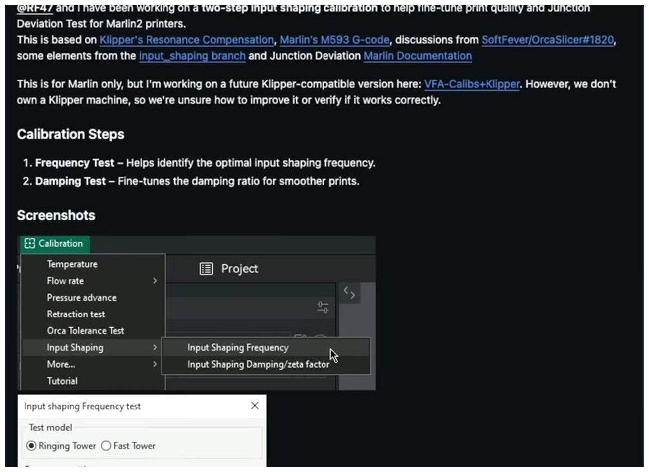
OrcaSlicer’s release notes from the 2.3 line announcing the Junction Deviation Test for Marlin2. The Calibration menu now has an Advanced submenu with Cornering alongside Input Shaper and VFA.
Menu path
Open OrcaSlicer with your printer profile loaded. The menu path is Calibration → Advanced Calibrations → Cornering. The in-app label is “Cornering (Jerk & Junction Deviation)” in the wiki, though the menu may show just “Cornering” depending on your build. If you’re running an older 2.3.0 build the entry may sit one level higher under the main Calibration menu. Either way, look for the word Cornering.
Firmware auto-detection
This is the smart part of the test. OrcaSlicer reads your printer profile’s G-code flavor and selects the parameter to sweep automatically. The behavior breaks down like this:
- G-code flavor Klipper: the test sweeps square_corner_velocity by injecting SET_VELOCITY_LIMIT commands between bands.
- G-code flavor Marlin 2 with Maximum Junction Deviation greater than 0 in Printer Settings → Motion ability → Jerk limitation: the test sweeps Junction Deviation in mm using M205 J commands.
- G-code flavor Marlin 2 with Maximum Junction Deviation set to 0: the test falls back to Classic Jerk in mm/s using M205 X and Y commands.
- G-code flavor RepRap/Duet: the test sweeps M566 instantaneous speed change in mm/s.
This is why the menu entry is called “Cornering” instead of “Junction Deviation.” It adapts. If you misconfigure your G-code flavor, for example by importing a printer profile from PrusaSlicer that ended up flagged as Marlin when your machine actually runs Klipper, the test will inject M205 commands that Klipper silently ignores. Every band on your tower will print identically and you’ll think your printer is magically tolerant of any setting. It isn’t. Check your G-code flavor before you commit to a four-hour print.
Default test parameters
The Cornering dialog exposes Start, End, and Step fields you can override. The defaults sweep a wide enough range that most printers find their value in one run.
| Sweep type | Default start | Default end | Default step |
|---|---|---|---|
| Junction Deviation (Marlin 2) | 0.00 mm | 0.25 mm | 0.005 mm |
| Classic Jerk (Marlin) | 5 mm/s | 20 mm/s | 0.5 mm/s |
| square_corner_velocity (Klipper) | 2 mm/s | 15 mm/s | 0.5 mm/s |
| M566 (RepRap) | 5 mm/s | 30 mm/s | 1 mm/s |
Prerequisites the dialog enforces
OrcaSlicer’s wiki and the dialog itself spell out three hard requirements. Skip any of them and the test gives you a misleading result.
- Acceleration high enough to trigger ringing. The recommended minimum is 2000 mm/s². If you run the test at 800 mm/s² because your old i3 clone can’t go higher, the printer will never hit the corner hard enough to round it and every band will look fine. The test isn’t measuring corner quality at low accel, it’s stress-testing the planner at the accel and speed you’ll actually print at.
- Outer wall speed high enough to trigger ringing. The recommended minimum is 100 mm/s. Below that, same problem as above. Corners that are too slow to round look the same as corners that are perfectly tuned.
- Opaque, high-gloss filament. This is non-negotiable for reading the result. Matte filaments hide ringing; translucent filaments make it hard to see corner shape. Black PLA Pro and red PLA are the community favorites because the surface sheen makes ghosting visible. Don’t run this test on a satin or matte spool and expect to read it accurately.
If you haven’t already run the input shaper calibration, do that first. Cornering and input shaper are related but separate, and tuning JD or SCV without IS active means you’re measuring resonance instead of the cornering limit. I’ll come back to this interaction in detail.
Test geometry
The model is a ringing-tower-style print. Vertical walls with sharp 90 degree corners on every layer, so any rounding or overshoot at the corner becomes visible as you climb the tower. Each band of layers uses a different cornering value, printed at the elevated acceleration and outer-wall speed you set in the dialog. You end up with a tower that looks like a series of stacked rectangular prisms, each one a slightly different cornering setting. Print time is typically 90 to 120 minutes on a CoreXY at 2000 mm/s² and 100 mm/s outer wall.
Reading the printed tower
Once the tower is off the bed, you read it bottom to top. The bottom band is the lowest cornering value, the top is the highest. Find the highest band where the corner is still sharp and free of artifacts. That value is your printer’s calibrated cornering setting.
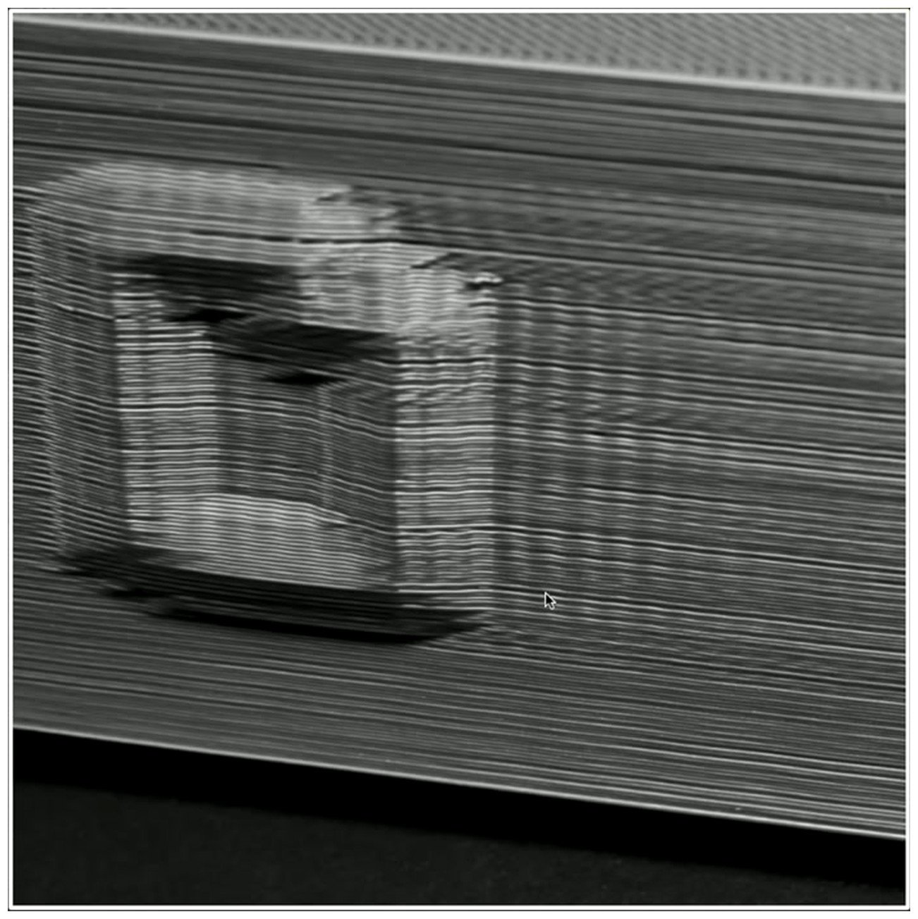
This is what you don’t want. Ringing artifacts on the wall after the 90 degree corner, where the planner pushed through the junction faster than input shaper or the frame can handle.
Here’s what each visual outcome means and how to act on it.
| What you see on the band | What it means | What to do |
|---|---|---|
| Sharp, clean 90 degree corner with no ghosting | JD or SCV is within limits at that band | Keep climbing the tower |
| Visible rounding of the corner, like a small chamfer | JD or SCV too high. The planner is cutting the corner. | Cap your setting one band below where rounding starts |
| Ghosting or ringing on the wall after the corner | Resonance. Input shaper not tuned, or jerk is still active alongside JD. | Stop. Retune input shaper calibration first, then redo this test. |
| Layer shifts appearing on higher bands | Combined accel plus cornering plus speed is overloading steppers | Lower acceleration, redo. Possibly raise stepper current too. |
| Audible stuttering and deceleration at every corner | JD or SCV too low for the print speed | Raise it. The firmware is decelerating to a crawl at every junction. |
| Bulges at corners, extra material at the apex | Pressure Advance tuning issue, not cornering | Retune PA first, then re-check cornering |
| Gaps right after the corner, under-extrusion | PA too high, or cornering too slow letting filament ooze | Tune PA, then re-check cornering. The OrcaSlicer troubleshooting guide has the diagnosis flow. |
The Voron forum’s “Square corner bulges plus low PA corner gapping” thread is the canonical reference for the PA-versus-SCV interaction. If you see bulges, fix PA first. If you see rounding, fix cornering. They look different in person but identical in low-quality photos, so I always look at the corner in raking light before I diagnose.
Picking the value
Take the value one band below where rounding starts. That’s your conservative buffer for filament variation, temperature drift, and the difference between the test geometry and real prints. If your tower shows rounding starting at the 0.06 band, save 0.055 or 0.05. If every band looks sharp, your sweep range was too conservative and you need to raise the End value and reprint. If every band looks rounded, your acceleration is too low to stress the printer and you’re not actually measuring anything.
Marlin integration and saving the value
On Marlin 2.x with CLASSIC_JERK disabled, the Cornering test outputs M205 J commands between bands. Marlin parses those at runtime and updates the planner’s JD value live. No EEPROM writes during the test, which is what you want; nothing gets permanently set until you decide.
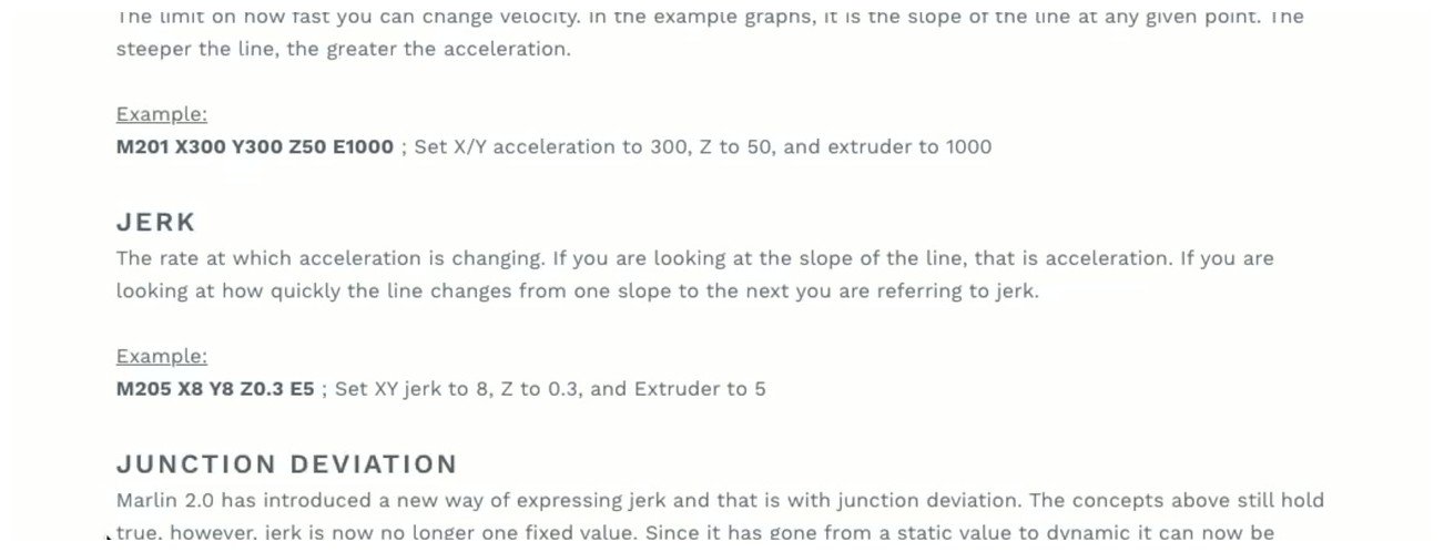
Marlin’s M205 page is the canonical reference for runtime JD and jerk control. The J parameter sets Junction Deviation in mm; X and Y set Classic Jerk in mm/s when CLASSIC_JERK is enabled.
The relevant Configuration_adv.h snippet looks like this on a stock Marlin 2.1.x:
// Junction Deviation Factor
#define JUNCTION_DEVIATION_MM 0.013

// Use Junction Deviation instead of Jerk Limiting
//#define CLASSIC_JERK
Junction Deviation has been the Marlin default since PR #15481 was merged in October 2019. The 0.013 mm value is deliberately conservative so that older non-tuned printers don’t fling themselves off the bed; tuned builds almost always end up between 0.02 and 0.08. To set JD at runtime from a slicer or terminal:
; Set Junction Deviation to 0.04 mm
M205 J0.04

; If using Classic Jerk instead, set X and Y jerk separately
M205 X10 Y10
If you want the value persistent across reboots, run M500 after M205 to save to EEPROM, or edit Configuration_adv.h and reflash. Most users don’t bother because saving in the OrcaSlicer printer profile is enough; the slicer injects the M205 command in the start G-code on every print.
The Klipper SCV gap and how to work around it
This is where I have to be honest about a limitation. OrcaSlicer’s cornering test was designed primarily around Marlin’s Junction Deviation model. Klipper users get partial support; the test can inject SET_VELOCITY_LIMIT SQUARE_CORNER_VELOCITY commands between bands, but the dialog still talks in JD-style units in older builds and the workflow isn’t as clean as the Marlin side.
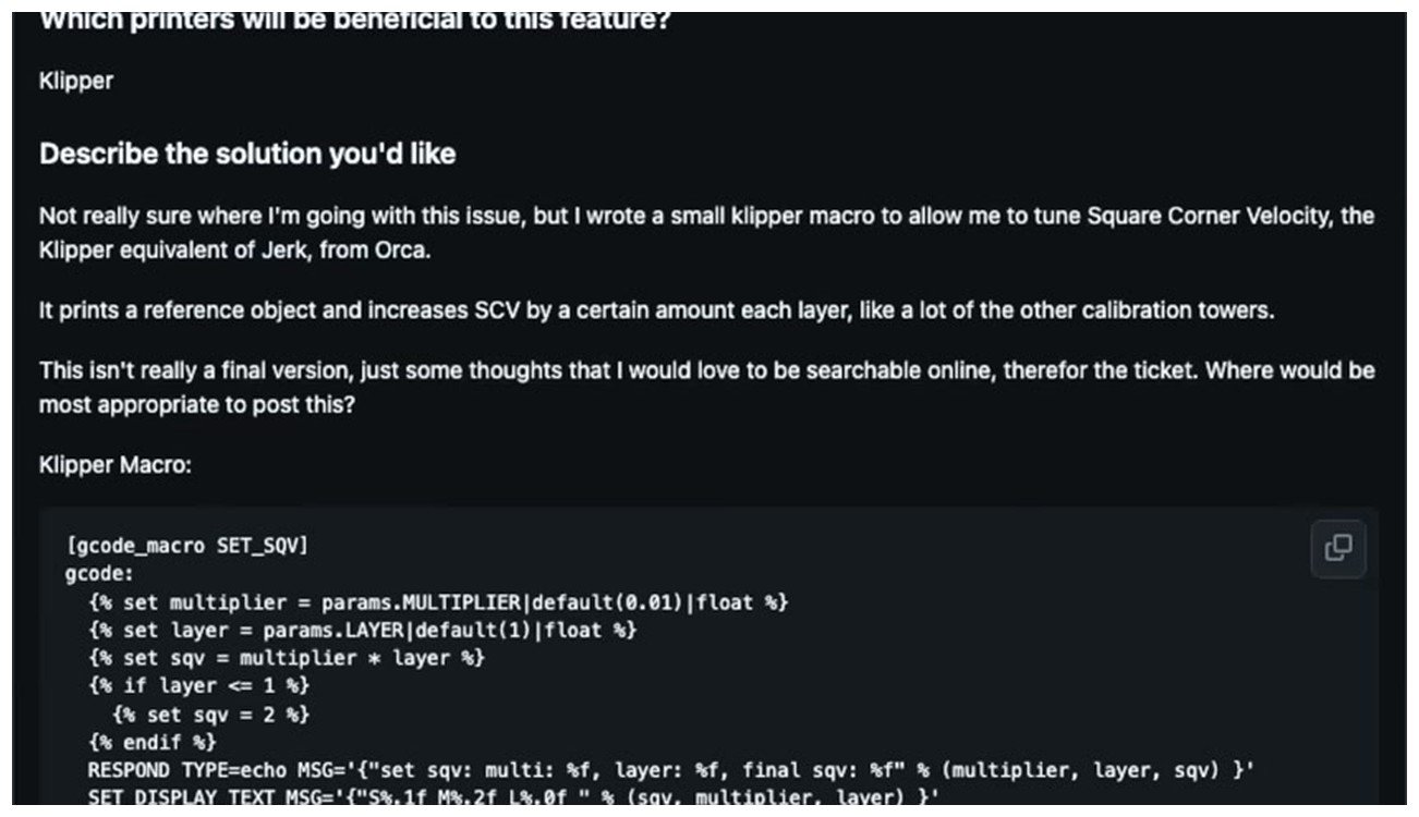
OrcaSlicer Issue #4220 tracks the open request for a first-class Klipper SCV calibration. Community macros like SET_SQV bridge the gap until a native test ships.
OrcaSlicer Issue #4220, “Calibration tool for Klipper Square Corner Velocity,” is the live tracker for this gap. As of the 2.3.2 build the issue is still open. What this means in practice for Klipper owners is:
- If your G-code flavor is correctly set to Klipper in your OrcaSlicer printer profile, the test injects SET_VELOCITY_LIMIT SQUARE_CORNER_VELOCITY commands and works as expected.
- If your G-code flavor is set to Marlin (common when importing profiles from PrusaSlicer or community Voron configs), the test injects M205 J commands which Klipper silently ignores. Your tower prints with identical bands. Switch the flavor in Printer Settings → General → G-code flavor and reprint.
- If you want finer control than the OrcaSlicer dialog provides, the community workaround is to tune SCV interactively. The pattern: print a tall test cube at your real print speed and acceleration, and override SCV mid-print via the Klipper console.
For the interactive route, the relevant Klipper printer.cfg block looks like this:
[printer]
kinematics: corexy
max_velocity: 350
max_accel: 10000
square_corner_velocity: 5.0
To override SCV live during a print, send this through the Klipper console or Mainsail/Fluidd terminal:
SET_VELOCITY_LIMIT SQUARE_CORNER_VELOCITY=8Watch the next few corners. Raise or lower in increments of 1 mm/s. When corners visibly round, back off by 1 mm/s and that’s your value. Edit printer.cfg to make it persistent, or set it in a SAVE_VARIABLES section if you prefer. The Klipper Discourse thread “Square Corner Velocity: what is the reasonable range of values” has community datapoints; users on Voron 2.4 typically run SCV between 5 and 15 mm/s depending on input shaper and frame stiffness.
If you want to translate a Marlin-style JD result to an SCV value, the conversion is the sqrt(2 * JD * acceleration) approximation from earlier. At max_accel 10000 mm/s² a tuned JD of 0.04 mm corresponds to SCV around 28 mm/s, which is well above the 5 mm/s default. But this is where Klipper’s input shaper warning kicks in and tells you not to raise SCV that high. Read the next section before you change anything. For broader Klipper setup specifics, the configuring OrcaSlicer for Klipper guide covers G-code flavor and config syncing.
Input Shaper and SCV, the warning nobody reads
I want to spend a section on this because the relationship between input shaper and cornering settings is the single most-misunderstood part of high-speed tuning. The Klipper docs are explicit about it, and almost every tuning YouTube video glosses over it.
Input shaper and JD/SCV are not the same thing. Input shaper cancels mechanical resonance caused by acceleration changes; it’s a feedforward filter applied to motion commands. JD and SCV control how aggressively the planner schedules cornering moves in the first place. They interact but they’re not interchangeable.
Without input shaper, raising JD or SCV means the printer flings through corners faster, exciting frame resonance, and you see ghosting and ringing on the wall downstream of the corner. With input shaper tuned, the same JD or SCV produces less ringing because the shaper cancels it. So tuned IS lets you push JD or SCV higher without quality loss. So far, intuitive.
Here’s the catch. Klipper’s Resonance Compensation documentation specifically warns against raising SCV above the default 5 mm/s when input shaper is active. The exact quote from the Klipper docs: “another parameter that can impact smoothing is square_corner_velocity, so it is not advisable to increase it above the default 5 mm/sec to prevent increased smoothing.” The reasoning is that SCV interacts with the input shaper’s smoothing window. Raising SCV makes input shaper smear out edges more, because the shaper has to extend its filter further to compensate for the faster corner traversal. You gain corner speed but lose edge crispness elsewhere.
This is a Klipper-specific warning. Marlin’s JD does not interact with Marlin’s ZV input shaper in the same way because Marlin’s smoothing math is different (Marlin has its own input shaper as of recent 2.1.x but the implementation differs from Klipper’s). Marlin users can raise JD with IS enabled and not see the same edge-smearing tradeoff.
So the practical guidance for Klipper users with input shaper enabled:
- Leave SCV at the default 5 mm/s. Don’t raise it.
- Get your cornering speed up by raising max_accel instead, since cornering speed is a function of both SCV and acceleration.
- If you genuinely need higher SCV (some users on extremely rigid Voron builds do), raise it carefully and watch for loss of edge sharpness on small details, not just corners.
For Marlin users with input shaper, the tradeoff is gentler but the tuning order still matters. Always tune Input Shaper first. The reason is that IS changes the maximum useful acceleration; cornering speed is a function of acceleration and JD/SCV; so any IS retune invalidates a prior JD calibration. The correct sequence is IS first, then JD or SCV at the new max acceleration.
Saving the value in your OrcaSlicer printer profile
Once you’ve picked a value off the tower, you save it in the OrcaSlicer printer profile so it travels with your slicer settings instead of living only in firmware. This is what the OrcaSlicer wiki recommends, and it’s what I do on all my machines.
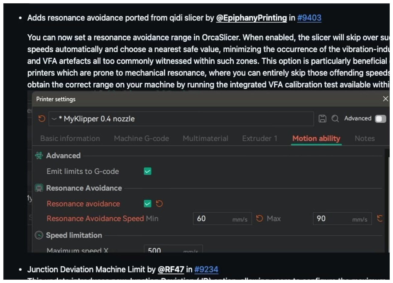
Printer Settings → Motion ability is where the calibrated values live. Maximum Junction Deviation for Marlin builds, and the Jerk X/Y/Z/E fields for Classic Jerk if you’ve kept that model. Resonance Avoidance is a separate feature; don’t confuse it with cornering.
The path is:
- Open OrcaSlicer with your printer profile loaded.
- Click the gear icon next to the printer dropdown to open Printer Settings.
- Go to Motion ability in the left sidebar.
- Find the Jerk limitation section.
- For Marlin JD: set Maximum Junction Deviation to your calibrated value (for example 0.04 mm).
- For Classic Jerk: set the Jerk X, Y, Z, E fields individually.
- For Klipper SCV: this is where it gets awkward; there’s no first-class SCV field in older builds. The convention is to save the JD-equivalent value here so OrcaSlicer’s time estimator uses it, then write the actual SCV to your printer.cfg separately.
- Save the printer profile.
OrcaSlicer’s start G-code will inject the appropriate M205 or SET_VELOCITY_LIMIT command on every print based on this value. No EEPROM writes needed, no firmware reflash, and the value moves with the slicer profile if you set up the same printer on another machine.
Common mistakes and edge cases
A few categories of mistake I see often enough on r/OrcaSlicer and the Voron Discord that they’re worth flagging explicitly.
Running the test with G-code flavor set wrong
The most common one. If you import a printer profile from PrusaSlicer or use a community profile from GitHub, the G-code flavor might be Marlin while your actual printer runs Klipper. The Cornering test will inject M205 commands that Klipper silently drops. Every band on the tower prints identically and you’ll think every value is fine. Always verify Printer Settings → General → G-code flavor matches your firmware before running this test.
Skipping input shaper tuning first
If IS isn’t tuned, the cornering test is measuring ringing rather than the cornering limit. You’ll see ghosting on every band above the lowest few, conclude that JD or SCV needs to be low, and end up with a conservatively-tuned printer that’s slower than it should be. Tune IS first. Always.
Bambu users running a test that does nothing
I covered this in the audience section but it bears repeating. The X1C, P1S, A1, and H2D run Bambu’s proprietary motion planner. Junction Deviation in the OrcaSlicer profile for Bambu machines affects time estimation only, not runtime planner behavior. Running the cornering test on a Bambu produces a tower where every band looks identical because the firmware overrides whatever JD value the slicer injects. This is not a calibration that benefits Bambu owners.
Confusing corner bulges with cornering issues
Bulges at the apex of corners, where there’s extra material right at the 90 degree point, look like a cornering problem but are almost always a Pressure Advance problem. PA controls how the extruder backs off and recovers during velocity changes; corners are where velocity changes hardest. If you see bulges, retune PA before you touch cornering. The corner-bulge-versus-corner-gap distinction is in the Voron forum’s canonical thread on the topic.
Layer shifts at the top of the tower
If the tower starts fine and shifts at higher bands, you’re hitting a combined accel-plus-cornering-plus-speed limit that’s overloading your steppers. The fix isn’t lower JD; it’s lower acceleration, lower speed, or higher stepper current. Don’t read a layer shift as a cornering result, read it as “my hardware can’t handle this combination” and recalibrate downstream.
Forgetting that JD interacts with the max acceleration you actually print at
If you calibrate JD at 2000 mm/s² accel but then bump your acceleration to 5000 mm/s² for a fast print, your effective cornering speed at that JD value just doubled and corners will round again. JD is a tolerance, not a speed limit; the speed it allows depends on the acceleration you give it. Re-test JD whenever you change max_accel meaningfully.
FAQ
Junction Deviation vs Classic Jerk, which should I use?
Junction Deviation, every time, on any Marlin 2.x build. JD adapts the cornering speed to the corner angle, which is what you want; Classic Jerk doesn’t. Marlin disabled CLASSIC_JERK by default in 2019 for exactly this reason. The only situation where Classic Jerk makes sense is if you’re stuck on a Marlin 1.x build that doesn’t have JD support.
What’s a “good” JD or SCV value for my printer?
There isn’t a universal one. The Marlin default 0.013 mm is conservative; tuned Marlin Vorons typically end up between 0.02 and 0.08 depending on frame and acceleration. The Klipper default 5 mm/s is what most Klipper-with-IS users should leave alone; Voron builds without IS or with very rigid frames sometimes push SCV to 8 to 12. Don’t copy someone else’s number. Run the test.
Should I tune cornering before or after Pressure Advance?
After. Tune PA first, because corners are where PA is most visible and you need PA stable before you can read corner shape correctly. The full calibration order I use is on the OrcaSlicer calibration master guide but the short version is: temperature tower test, flow rate calibration, Pressure Advance tuning, retraction test, max volumetric speed test, input shaper calibration, cornering, tolerance fit test, VFA.
Why does my Bambu printer ignore the JD value in my OrcaSlicer profile?
Because Bambu’s firmware doesn’t expose Junction Deviation or jerk as runtime parameters. The motion planner is closed and Bambu handles cornering internally. The JD field in OrcaSlicer’s Bambu printer profiles is a time-estimation hint that was added in 2.3.2 so print time estimates would account for cornering deceleration; it’s not a runtime control. There’s a long thread on the Bambu Lab community forum about this.
Does cornering calibration affect print time?
Sometimes, marginally. A higher JD or SCV means the printer decelerates less at corners, so prints with lots of corners (small details, hexagonal infill, dense walls) run slightly faster. On a typical large print with mostly long straight walls the difference is under 2 percent. The bigger gain is print quality, not time.
Why does my OrcaSlicer cornering tower show identical bands all the way up?
Three possibilities, in descending order of probability. One, your G-code flavor is set wrong and the firmware is ignoring the M205 or SET_VELOCITY_LIMIT commands the slicer is injecting. Two, your printer is Bambu and the firmware overrides external cornering inputs. Three, your acceleration is set too low to stress the planner, so even the most aggressive JD value doesn’t produce visible rounding because the printer never reaches the speed where rounding matters.
Do I need to redo this test after upgrading my hotend or extruder?
Not for the hotend; cornering is a motion planner setting, not an extruder setting. You will need to redo it if you change anything that affects the moving mass or frame stiffness: toolhead swaps, lighter or heavier hotends, belt tension changes, frame rigidity changes from a new chassis or stiffening kit. Anything that changes the resonance picture means input shaper needs retuning, which means cornering needs retuning after that.
Can I use the same JD value across all my OrcaSlicer profiles for the same printer?
Yes, JD is per-printer not per-filament. Save it once in Printer Settings → Motion ability → Jerk limitation and every filament profile on that printer will use it. The only reason to vary it would be if you swap toolheads or run very different print speeds across profiles, in which case you might want a conservative profile and a fast profile with different JD values.
Next steps
If you’ve finished this calibration and want to push print speed further, the next steps from here depend on what you’re trying to improve. For raw flow ceiling, run the max volumetric speed test next. For finer feature quality, the tolerance fit test and VFA test cover the small details. For ringing that survived input shaper and cornering tuning, the input shaper calibration page has the deeper troubleshooting flow. And if any of the diagnoses in this article led you somewhere weird, the OrcaSlicer troubleshooting guide indexes the symptoms back to their root causes.
The pillar that ties all of this together is the OrcaSlicer calibration master guide. I keep my standard calibration sequence in that order: temperature, flow rate, pressure advance, retraction, max volumetric speed, input shaper, cornering, tolerance, VFA. Cornering sits near the end on purpose, because everything upstream affects what a good cornering value looks like. Skip the order at your own risk; do the order in order and you’ll spend less filament getting there.
Related OrcaSlicer guides
- The Complete OrcaSlicer Calibration Guide (Order Matters)
- OrcaSlicer Tolerance & Fit Test: Functional Parts (2026 Guide)
- OrcaSlicer Retraction Test: Solving Stringing in 30 Minutes
- OrcaSlicer Input Shaper Calibration for Klipper (2026 Guide)
- OrcaSlicer Bed Adhesion Problems: Glue Strategies & Real Fixes (2026)