
I designed a snap-fit case for an Arduino Mega last month, slid the lid on, and it bound up so tight I had to break it back off with pliers. The CAD was perfect, the printer was calibrated, but the OrcaSlicer X-Y hole compensation was still at the default 0 mm. One tolerance test print and a 0.1 mm offset later, the lid clicked together like it should. This is the calibration most people skip until they need it, and then they’re sitting at the workbench wondering why a 10 mm hole that measures 9.85 mm on the calipers won’t pass an M3 bolt.
If you print functional parts, especially anything with mating geometry, you cannot get away without running a fit test at least once per filament. Not “should”. Cannot. The whole reason the test exists is that no two printers produce the same hole at the same dimension, and no two filament rolls shrink the same way. The Bambu wiki, the Obico guide, and most YouTube walkthroughs gloss over what to do with the result. I’m going to be specific.
This guide walks through the OrcaSlicer Tolerance Test from menu click to bolted-down enclosure. It covers the hex test model itself, the math behind XY hole compensation, per-material shrinkage, the three fit types you’ll actually use in CAD, and the upstream calibration issues that quietly poison your tolerance result before you ever start. If you haven’t done the rest of the calibration stack first, head over to the OrcaSlicer calibration guide and come back when flow and pressure advance are dialed.
Table of Contents
- Why functional parts need a fit test at all
- The Orca tolerance test model, what it actually is
- Running the tolerance test in OrcaSlicer, step by step
- Reading your result without spiraling
- The three fit types and the gap each one needs
- XY Hole vs XY Contour Compensation, explained
- Applying the compensation value in the slicer
- CAD-baked tolerance vs slicer compensation
- Per-material shrinkage and what changes
- Upstream causes that wreck the test
- Real forum pain points, real fixes
- Wrap, and what to calibrate next
Why functional parts need a fit test at all
Decorative prints forgive you. A vase or a low-poly fox doesn’t care if its silhouette is 0.15 mm wider than the CAD. Functional parts are different. A snap-fit lid that’s 0.2 mm too tight cracks at the corner. A printed gear with a 5.05 mm bore won’t slide onto a 5 mm shaft. An M3 clearance hole that prints at 3.1 mm instead of 3.4 mm bottoms out the bolt head before the threads even engage. Tolerance isn’t an aesthetic concern. It decides whether the part works.
Here’s what’s actually happening. When the nozzle traces a closed hole, the molten plastic curls slightly inward as it cools. The hole shrinks. On the outer contour of a part, the same physics applies, except now the curl pulls the outer dimension inward too. So a 10 mm peg ends up at 9.95 mm and a 10 mm hole ends up at 9.85 mm, and your beautifully-matched CAD doesn’t assemble. It’s not the printer being broken. It’s basic thermal contraction plus extrusion path geometry, and every FDM printer has it to some degree.
The tolerance test gives you a single number that tells you how much your printer overshoots inward on hexagonal recesses. From that number, you decide whether to fix it in CAD or in the slicer, and which fit type each feature of your design needs. Without the test, you’re guessing, and guessing on functional parts wastes filament and bench time. I’ve burned through entire afternoons reprinting a single bracket because I didn’t bother to run a 20-minute calibration.
The Orca tolerance test model, what it actually is
OrcaSlicer ships with a built-in tolerance test model. It’s a flat base with six hexagonal recesses, each one sized at a different positive offset from a printed hex tester. The offsets are 0.00 mm, 0.05 mm, 0.10 mm, 0.20 mm, 0.30 mm, and 0.40 mm. The tester is a printed hexagon shipped with the model, and a standard 6 mm Allen key fits the same socket if you’d rather use that.
The choice of hex over a round peg-and-hole isn’t aesthetic. Round holes hide error. A 10 mm circular hole that prints as 9.85 mm with a slightly oval cross-section can still pass a peg test if the peg is also slightly oval in the same orientation. The two errors cancel. Hexagons don’t let you cheat that way. A hex hole has six straight wall segments and six corners, and the corners are where extrusion is hardest to control. If the corner radius blunts inward, the tester won’t drop in regardless of how the rest of the hole looks.
It also matches real CAD design intent. Nut traps for M3 nylock nuts, hex sockets for cap screws, knurled brass inserts, snap-fit pawls. They all have flat reference faces. Testing a hex shape gives you data that directly applies to the parts you actually print. If your printer can pass a 0.10 mm hex tolerance, your M3 nut traps will work at +0.10 mm clearance too.
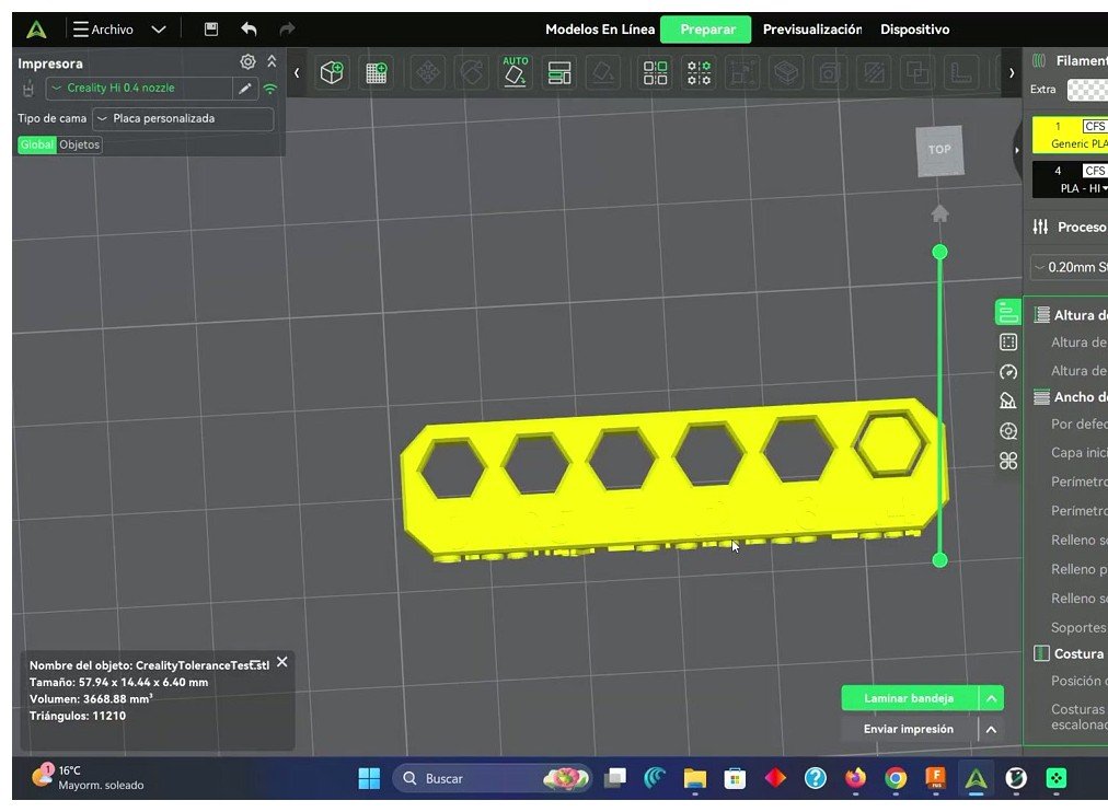
The Orca tolerance test loaded on the build plate. Six hex recesses on the base, one hex tester to the side. Plate orientation matters less than you’d think because the test is symmetric, but keep the tester flat to the bed.
Running the tolerance test in OrcaSlicer, step by step
There are two ways to load the model. Both end up in the same place.
Route A, calibration menu. Open OrcaSlicer, click Calibration in the top menu, then Tolerance Test. The model loads as a fresh project on the active build plate, with the tester already positioned alongside the base. This is the easier of the two routes.
Route B, plate context menu. In Prepare mode, right-click anywhere on the build plate and choose Add Handy Model. Pick the tolerance test from the dropdown. This is useful if you want to add the test to an existing project rather than starting fresh, or if you want to drop in two copies for comparison.
Before you slice, do these things in order. Skip any of them and you’ll get a misleading result.
- Use the printer profile and filament you’re actually testing. The tolerance result is filament-specific. PLA at 215 C with brand A gives you a different number than PLA at 200 C with brand B. Don’t run the test in your “generic PLA” profile and apply the result to Polymaker PolyTerra. It won’t transfer cleanly.
- Zero out both compensation values. Go to Process settings, then Quality, then Precision. Set
X-Y Hole Compensationto 0 mm andX-Y Contour Compensationto 0 mm. The Obico guide flags this explicitly, and it’s the single most common mistake. If either value is non-zero when you run the test, you’re measuring your settings, not your printer. - Standard layer height. Use 0.20 mm on a 0.4 mm nozzle. Don’t try to “be safe” with 0.08 mm. Finer layers introduce their own variables (pressure advance behaves differently, line width effects shift). Match what you’ll actually print functional parts at.
- Default wall count. Two outer plus one inner is the standard Orca default. Don’t crank to four walls hoping for accuracy. The compensation behavior depends on wall count near small features, and you want the test to reflect your normal slicer config.
- Leave Precise Wall on. The default in 2.3.x is
true, and that’s what you want. Precise Wall adjusts outer wall spacing to improve dimensional consistency. Turning it off here would defeat half the point of testing. - Confirm flow and pressure advance are tuned. If either is off, the tolerance test result is meaningless. Run flow rate calibration and pressure advance first. I cannot stress this enough. I’ve seen tolerance threads on GitHub where the actual fix was flow ratio off by 4%.
Slice, print, and wait for the part to cool fully before testing. PLA needs about 30 minutes after the print finishes to stop dimensional creep, PETG closer to 60 minutes, ABS 90 minutes or more depending on whether you’ve got an enclosure. Yank a hot PETG print off the bed and try to fit the tester immediately, and you’ll get readings that change overnight. Don’t trust hot measurements.
Reading your result without spiraling
Once the print is cool, take the tester (or a 6 mm Allen key) and try each hole, starting from the largest offset (0.40 mm) and working down toward zero. Note where the fit changes character. There are basically three states.
- Drops in freely. Tester slides in without friction. That’s a clearance fit at that offset.
- Goes in with friction. You have to push, but not crush. Slip fit or transition fit.
- Won’t go. Tester binds before it seats, or you’d have to hammer it. Press fit (or interference, depending on how hard).
The number you care about is the smallest offset where the tester drops in cleanly. That’s your printer’s effective XY error for that filament. If 0.10 is the smallest one that works, your printer is overshooting inward by 0.10 mm on hex geometry. If 0.20 is the smallest one that works, you’re at 0.20 mm error. Anything above 0.25 mm or so means something upstream is wrong, and you should fix that before continuing.
The recurring question on the OrcaSlicer GitHub (discussion #1743) is “I got 0.2 mm. Now what?” The honest answer, repeated by SurgeHawk in that thread: the test is informational. It tells you what your printer can do. From there you have two valid moves.
- Design the gap into your CAD. If your printer needs 0.2 mm extra for a slip fit, model the hole 0.2 mm larger than the peg. Done. No slicer settings to remember.
- Apply XY hole compensation in OrcaSlicer. Set
xy_hole_compensationto half your measured deviation (because the value is a radial offset, not a diameter offset). For a 0.2 mm fit result, you’d set +0.10 mm. Now every hole in every model widens automatically.
Both work. I’ll cover when to use each below.
The three fit types and the gap each one needs
Tolerance is just a number until you turn it into a design decision. Engineering practice splits fits into categories, and each one needs a different gap between the peg and hole. These values are starting points, not laws. They assume your printer has been through a tolerance test and you know its baseline error. Add your printer’s measured offset to these gaps when designing.
| Fit type | Gap (peg vs hole) | Use case | Notes |
|---|---|---|---|
| Press fit / interference | 0.00 to 0.05 mm | Permanent assembly, heat-set insert pre-holes, pinned hinges | Apply with steady even pressure. Avoid on PETG which cold-flows over time. |
| Snap fit | -0.05 to +0.05 mm at the snap, with chamfered lead-in | Battery covers, removable case lids, anything that needs a click | Add a 0.5 to 1.0 mm chamfer on hole entry. Small chamfer on peg tip helps too. |
| Slip fit / transition | 0.10 to 0.20 mm | Drawer slides, alignment pins, removable shafts | Light friction. Parts you want to take apart later. |
| Clearance fit | 0.20 to 0.40 mm | Hinges, bushings, rotating shafts, M3/M5 bolt clearance holes | Use the upper end for moving parts that need to spin freely. |
| Loose fit | 0.40 mm and up | Cable through-holes, vent slots, non-aligning bolt clearance | Forgiving. Use when accuracy doesn’t matter. |
For metric bolts, the ISO 273 clearance hole values are a useful starting point, but FDM users typically pad them slightly. Here’s a quick reference for clearance holes I’ve found reliable across a few different printers:
| Bolt size | ISO 273 medium clearance | Suggested FDM CAD hole |
|---|---|---|
| M2 | 2.4 mm | 2.5 to 2.6 mm |
| M3 | 3.4 mm | 3.5 to 3.7 mm |
| M4 | 4.5 mm | 4.6 to 4.8 mm |
| M5 | 5.5 mm | 5.6 to 5.8 mm |
| M6 | 6.6 mm | 6.7 to 6.9 mm |
The 0.1 to 0.3 mm pad above ISO accounts for the inward-curl effect on holes plus any first-layer squish that narrows the bottom of the hole further. If your tolerance test came back at 0.05 mm, you can use the lower end of these ranges. If it came back at 0.20 mm, use the upper end and you’ll have bolts that drop through cleanly without rattle. Snap-fits and press-fits are more sensitive and deserve their own test for each material.
One honest caveat. There is no universal correct number. The Prusa forum has a thread (a snap-fit one I keep going back to) where someone notes “what is loose for you may be too tight for someone else.” Your printer is not my printer. These values are starting points to get you in the ballpark on the first print rather than the third. Always verify with a real-fit test on the final material before committing to a batch.
XY Hole vs XY Contour Compensation, explained
OrcaSlicer exposes two compensation knobs. Most users mix them up. They do opposite things on purpose.
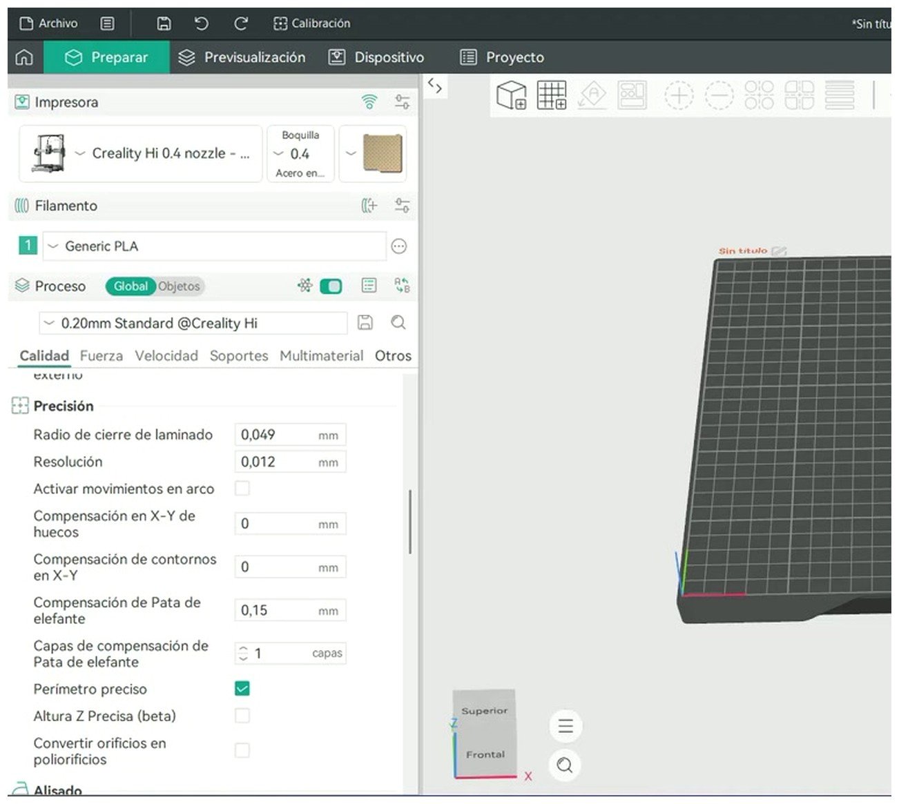
The Precision section under Process settings, Quality tab. Note this screenshot is in Spanish: “Compensación X-Y de huecos” is X-Y Hole Compensation, and “Compensación de contornos” is Contour Compensation. The English UI uses the same field positions in the same order.
xy_hole_compensation acts on inner closed contours, which means the holes that are fully contained on a given layer. Positive values widen the holes. Negative values shrink them. Default is 0 mm. The mode is Advanced, so you need to switch the parameter view to Advanced or expert to see it.
xy_contour_compensation acts on the outer silhouette of the part. Positive grows the outer dimensions, negative shrinks them. It does not touch holes. Default is also 0 mm, Advanced mode.
Why both exist instead of one global XY size knob? Because the inward-curl from cooling pushes material into holes (making them smaller) and pulls material inward on outer contours (also making outer dims smaller). Both effects shrink the part, but they shrink different geometry. A single “+0.05 mm everywhere” knob would help one and hurt the other. Splitting them lets you compensate independently.
The math is straightforward. If your tolerance test shows the tester drops cleanly into the 0.20 mm hex hole, your printer is overshooting inward by 0.20 mm on the hex diameter. Since the compensation value is a radial offset (applied to the toolpath, not the diameter), you set:
compensation = deviation / 2 = 0.20 / 2 = +0.10 mm
Set xy_hole_compensation to +0.10 mm and re-run the test. The tester should now fit cleanly at the 0.05 or 0.10 hole instead of 0.20. If it overshoots and the 0.00 hole is now loose, you’ve gone too far and need to back off to +0.08 or so. Real calibration is iterative.
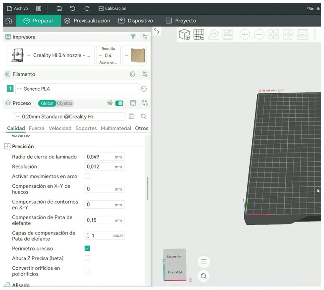
Zoomed view of the Precision settings. Both compensation values default to 0 mm. Set them here before running your tolerance test, and only adjust after you have a measured result.
A few gotchas worth flagging.
Don’t push hole compensation past ~0.15 mm. Issue #8011 on GitHub documents visible print artifacts that show up when hole compensation gets aggressive. The slicer’s path offset starts pulling material in unexpected directions, especially on holes larger than 8 mm. If you find yourself needing more than 0.15 mm, fix the underlying cause (flow rate, belt tension, line width) instead of stacking more compensation on top.
Hole compensation is a process setting, not a filament setting. Issue #3990 is an open request to make it filament-scoped. As of 2.3.x, it lives in the process profile. So when you switch from PLA to PETG, you need to either tweak the value manually or maintain separate process profiles per material. Annoying, but workable.
Never run hole and contour comp at high values simultaneously. The Kingroon writeup makes this point clearly, and it tracks with my experience. Apply hole comp first, retest, then add contour comp only if outer dimensions are still off. Stacking them both at +0.10 mm is asking for compound errors.
Compensation doesn’t affect horizontal holes. If you’re printing a hole that runs through the layer plane (a horizontal pin slot, say), the compensation values don’t touch it. Horizontal features need design-side gap, not slicer compensation.
Applying the compensation value in the slicer
With a measured result in hand, applying it is two clicks. Open Process settings, expand to Advanced parameter view if you’re not already there, navigate to Quality, find the Precision subsection, and click into the X-Y Hole Compensation field. Type your calculated value. Save the profile under a new name if you want to keep the default available.
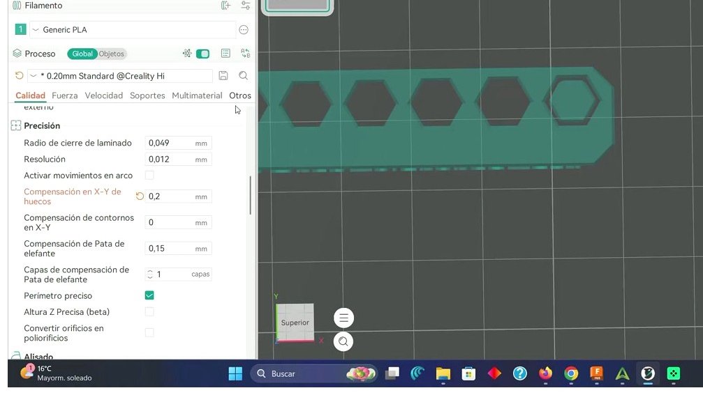
The X-Y Hole Compensation value edited to a non-zero number (here 0.2 in the localized comma-decimal format). Save your profile under a clear name like “PLA Brand A with hole comp 0.10” so you remember which material it’s tuned for.
A note on profile hygiene. Because compensation is process-scoped right now, the cleanest workflow is to clone your base process profile for each filament you’ve calibrated, name them clearly, and apply the matching compensation in each clone. So “0.20 mm Standard PLA Polymaker” and “0.20 mm Standard PETG Polymaker” become separate profiles with different hole comp values. Slow to set up, fast to use later.
Reslice the tolerance test with the new value and reprint. The tester should now fit at a tighter hex (smaller offset) than before. Repeat until you’re happy. Two or three iterations usually gets you within 0.02 mm of perfect, which is the noise floor of FDM anyway.
CAD-baked tolerance vs slicer compensation
Two valid approaches. Both work. Pick by use case.
Bake the gap into CAD. Design your peg at nominal (10 mm) and your hole at nominal plus your fit gap (10.20 mm for a slip fit, for example). The STL carries the gap with it. Anyone printing the model on a similar machine in similar material gets the right fit. No slicer settings to remember, no hidden config that breaks when someone else slices it.
Pros: portable across slicers and printers. STLs stand on their own. Open-source projects almost always do it this way.
Cons: tied to one filament family. The same STL won’t fit right if you print it in ABS instead of PLA because shrinkage differs.
Use slicer XY hole compensation. Design both parts at nominal (10 mm peg, 10 mm hole). Set xy_hole_compensation to your calibrated value. The slicer widens the hole on the way to G-code.
Pros: flexible. Switch materials, switch compensation, same CAD. Great for prototyping where you’re iterating mating geometry and don’t want to keep editing dimensions.
Cons: anyone else printing your STL gets a different fit unless they know your settings. Compensation values are easy to forget when you come back to a project six months later.
Honest take: CAD-baked tolerance is more portable than slicer compensation. Both have their place. For parts I’m publishing on Printables or Thingiverse, I always bake the gap in CAD so anyone can print them and get a reasonable result without needing to mirror my Orca profile. For one-off prototypes where I’m tweaking fit between print runs, the slicer compensation route is faster because I’m not rebuilding the model every time.
The best-practice production workflow combines both. Design at nominal in CAD, add the fit gap per the table above, leave slicer compensation at zero, and run a final fit test in the actual production filament before printing a batch of parts. That way the STL is portable and the slicer config is clean.
Per-material shrinkage and what changes
Material matters more than slicer settings for a lot of tolerance problems. Each filament shrinks differently as it cools, which means each one needs its own calibration pass. Here’s a rough reference for common materials, anchored against the OrcaSlicer issue #360 thread and a few independent measurements.
| Material | Typical linear shrinkage | Tolerance behavior | Recommended action |
|---|---|---|---|
| PLA | ~0.30% | Most stable common filament. Tests transfer between brands reasonably well. | Use measured value as-is. Re-check on new spool only if fit-critical. |
| PETG | ~0.40% | Higher shrinkage. Ooze halos around holes shrink them further. Cold-flows over time on press fits. | Add 0.05 to 0.10 mm extra clearance vs PLA. Avoid press fits. |
| ABS / ASA | 0.60 to 0.80% | High shrinkage. Tapered holes if printed without enclosure (top shrinks more than bottom). | Print in enclosure. Add 0.10 to 0.15 mm clearance vs PLA. |
| TPU | Variable | Compressive. “Fit” is subjective by feel, not by caliper. | Design oversize. Test by hand. Don’t trust slicer compensation. |
PLA is the easiest. The tolerance test result transfers between brands without much drama, and the standard fit-type gaps work straight off the table. If you’re prototyping mechanical parts and don’t have a reason to use something else, PLA is the right starting filament because it lets you focus on the fit math instead of the material behavior.
PETG is where most people get confused. The shrinkage is higher, but more importantly PETG sticks to itself during printing, leaving small “ooze halos” of stringy material around hole openings. Those halos effectively shrink the hole further. I usually add another 0.05 to 0.10 mm of clearance beyond what the tolerance test shows for PETG snap-fits because cleaning the halo by hand is inconsistent. Also worth knowing: PETG cold-flows over weeks. A press fit in PETG will gradually loosen. For anything that needs to stay tight, use a mechanical lock (snap, screw, threaded insert) instead.
ABS and ASA are the hardest. The 0.6 to 0.8% shrinkage is enough that an enclosed printer is mandatory for accurate parts. Without an enclosure, the bottom of a tall hole prints fine (still warm from adjacent layers) and the top shrinks more because it cools faster, giving you a tapered hole that the tester can’t fully seat in. Issue #360 on the OrcaSlicer repo was specifically opened to ask for filament-level shrinkage compensation for exactly this reason, and it’s still open. For now, calibrate in your actual print environment.
TPU defies most tolerance rules. It’s rubbery. Press fits feel different (compressive instead of interference). The hex tolerance test still gives you a usable number, but treat it as a starting point and verify by feel. Don’t bother measuring TPU holes with calipers, the material deforms under the jaw pressure.
One more thing worth saying clearly. Temperature affects shrinkage. PLA at 215 C shrinks slightly more than the same PLA at 200 C. If you change your temperature tower result, retest tolerance. If you change brand, retest. If you change spool color even (some pigments add fillers that change shrinkage), retest fit-critical parts.
Upstream causes that wreck the test
Before blaming the slicer for a weird tolerance result, check these. Any one of them can poison the test before you even start.
- Flow rate uncalibrated. Over-extrusion shrinks holes from the inside. Under-extrusion grows them. Run flow rate calibration first. If your flow ratio is off by more than 2%, the tolerance result won’t be stable.
- Pressure advance off. Under-tuned pressure advance bulges material at direction changes. Holes come out elliptical with the long axis in the print direction. Tolerance test results are unreliable until pressure advance is dialed.
- Loose belts or worn pulleys. Backlash makes every hole oversized in one axis. The input shaper test exposes belt and motion issues, and so does a tolerance test that gives different results on different orientations.
- First layer over-squished. Elephant foot at layer 1 narrows the bottom of every hole. The default for
elephant_foot_compensationis 0 mm. If your first layer is visibly bulged, dial in elephant foot comp at 0.10 to 0.20 mm before retesting tolerance. - Filament moisture. Wet PETG or ABS extrudes inconsistently and produces random hole sizes. Dry the filament before testing. If your spool’s been sitting in humid air for a week, you’ll get noise instead of a result.
- Line width too high. A 0.45 mm line width on a 0.4 mm nozzle pushes more material per pass, shrinking holes more aggressively. The Voron community typically keeps line width at 0.42 for dimensional accuracy. If your line width is 0.5+ on a 0.4 nozzle, lower it before retesting.
- Print speed too high. Beyond a certain speed, walls don’t have time to deposit cleanly. Tolerance test at 200+ mm/s with no calibration gives bad data. Use the same speeds you actually print functional parts at.
Also worth mentioning is cornering calibration. Jerk and junction deviation affect how sharp the corners of the hex hole turn out. If your cornering is set for vase mode, hex corners will be rounded inward and the tester won’t seat. Match cornering to the kind of geometry you actually print.
The honest workflow order is: temperature tower, flow rate, pressure advance, retraction, then tolerance. If you’ve jumped straight to tolerance without the prior steps, you’re skipping the foundation. The OrcaSlicer troubleshooting guide walks through the order in more detail if you need a refresher.
Real forum pain points, real fixes
These are the threads I’ve seen come up over and over on the OrcaSlicer GitHub and forums. If your symptoms match any of these, the fix is usually faster than starting from scratch.
“My snap-fit case is too tight at the corners but loose in the middle.” Classic corner-rounding problem. Either pressure advance is under-tuned (corners bulge inward) or line width is too high. Drop line width to 0.42 on a 0.4 nozzle, re-run pressure advance, then retest. Also add 0.5 mm chamfers at the lid entry, snap-fits hate sharp 90-degree lead-ins.
“M3 bolt won’t go through the clearance hole even though I designed it at 3.4 mm.” Your effective hole is probably 3.1 or 3.2 mm. Run the tolerance test, get your printer’s offset number, then either set xy_hole_compensation to half that offset or redesign the hole at 3.6 to 3.7 mm. If the hole is shallow, also check elephant foot, that narrows the bottom of every hole on layer 1.
“Threaded insert pre-hole is too small for the heat-set insert.” This one usually surprises people because brass inserts have specific spec sheets. The spec hole size assumes a perfectly dimensional part. On FDM, you need to add your tolerance offset to the spec. If the McMaster insert says “4.0 mm pre-hole” and your printer makes holes 0.15 mm undersized, design at 4.15 mm. Don’t try to muscle the insert into a too-small hole, you’ll crack the part.
The CrealityCloud thread where a K1 user with a 0.4 mm hardened steel nozzle and Sunlu PLA+ got 0.2 mm result and was disappointed is a useful real-world example. 0.2 mm on a stock K1 isn’t bad. It’s expected. The fix isn’t to chase 0.0 mm, it’s to set XY hole comp to +0.10 mm and move on. The same goes for the Bambu forum thread (t/9831) about parts not fitting. The fix is almost always: run the tolerance test, set compensation, redesign or reslice.
“I set XY hole compensation and now my large holes have weird scarring on the surface.” That’s issue #8011. You’ve gone too aggressive with the compensation value. Back it off to +0.10 or +0.08 and find the upstream cause (flow, belts, line width) for the remaining error. Compensation isn’t a magic fix, it’s a fine adjustment after the rest of the system is good.
“My tolerance result changed after swapping filament brands.” Expected. Each filament has its own shrinkage. Issue #3990 is the open request to make compensation filament-scoped, but until that ships, you need separate process profiles per material. Annoying, but realistic.
Wrap, and what to calibrate next
Tolerance calibration sits late in the OrcaSlicer calibration order on purpose. It depends on flow, pressure advance, retraction, and motion all being dialed first. If you’ve worked through the rest of the stack and you’ve now got a printer that produces hex holes within 0.05 to 0.10 mm of nominal, you can trust your functional parts. Snap-fit cases will click together on the first try. M3 bolts will drop through clearance holes. Brass inserts will press in cleanly.
A few things to keep in mind as you go. Tolerance is printer-specific. Your printer is not my printer, and neither of ours matches the YouTube tutorial’s printer. The numbers in this guide are starting points to get you in the right ballpark on the first iteration. Run the test, measure, adjust, repeat. Two to three cycles usually gets you to the noise floor of FDM, which is around 0.02 mm. Chasing tighter than that is wasted effort.
Per-material calibration is mandatory if you care about fit. PLA, PETG, ABS, TPU all shrink differently. Maintain separate process profiles, set hole compensation per profile, and label them clearly so you don’t reach for the wrong one six months from now.
Don’t forget the things tolerance compensation cannot fix. First-layer Z offset and belt tension affect dimensional accuracy independently of any slicer setting. If your first layer is over-squished, the bottoms of holes will always be tight regardless of what you set XY hole compensation to. If your belts are loose, holes will be oval. Slicer compensation is the last 5%, not the whole solution.
For what to calibrate next, head back to the OrcaSlicer calibration guide for the full pillar. If you haven’t yet tuned max volumetric speed or cornering, those are the next two stops. Both affect functional part quality in ways that show up alongside dimensional accuracy. And if you’re working on assembly-heavy projects, double-check your filament settings to make sure each profile has its own compensation values saved.
The Arduino case I started this article with prints reliably now. Lid clicks on, lid pulls off, no pliers required. It took one tolerance test, one compensation adjustment, and maybe 40 minutes of bench time total. For a calibration step most people skip, the payoff is bigger than almost anything else on the list. Run the test once per printer, once per material, and your future self will stop reprinting brackets.
Related OrcaSlicer guides
- The Complete OrcaSlicer Calibration Guide (Order Matters)
- OrcaSlicer VFA Test: Diagnose Vertical Fine Artifacts (2026 Guide)
- OrcaSlicer PA Line vs PA Pattern vs PA Tower: Which Pressure Advance Test (2026)
- How Often Should You Recalibrate OrcaSlicer? 2026 Maintenance Schedule
- OrcaSlicer Z-Wobble & Z-Banding: Diagnose and Fix (2026)