
The first time I really noticed it, I was holding a black ABS enclosure I’d printed overnight, and the base flared out a clean half-millimeter past the design. The model was 40.00 mm in Fusion, but my calipers read 40.6 at the base and 39.98 ten layers up. After a few weekends of changing one variable at a time, I finally figured out why OrcaSlicer’s compensation setting fixed it on PLA but barely dented it on PETG.
If you’re here, you’ve probably seen the same thing: a print that looks fine from chest height but obviously wrong under a desk lamp, with a soft outward swell on the first one to three layers. This guide walks through what’s actually happening, the OrcaSlicer settings that matter, per-filament starting values, and two non-slicer fixes that beat compensation on the parts they suit.
Table of contents
- What elephant foot actually is (and what it isn’t)
- Why it happens, over-squish meets bed heat
- The OrcaSlicer setting: elefant_foot_compensation
- Companion settings: compensation layers and layer density
- Per-filament starting values (community ranges)
- First-layer flow vs walls: the bottom_solid_infill_flow_ratio trap
- Z-offset and ABL: why ABL is not a fix
- The CAD chamfer-bottom alternative
- Why brim, raft, and skirt don’t fix it
- Troubleshooting checklist and FAQ
What elephant foot actually is (and what it isn’t)
Elephant foot is a visible outward bulge on the first one to three layers of a print. The base comes out wider than the rest of the geometry, and from the side the silhouette looks like a flared boot. It’s a first-layer geometry defect, and the giveaway is that calipers read oversize only near the build plate while upper layers measure correctly.
I want to draw a line between this and plain old first-layer over-squish, because the two get blamed for each other constantly. Over-squish is when the entire first layer is mashed flat by a nozzle set too low, and you’ll feel it as a glossy surface on the bottom of the part. Elephant foot is the geometric consequence of that over-squish (and a hot bed), but they aren’t the same symptom. You can have a perfectly textured first layer and still get elephant foot on PETG because of bed heat alone. I’ve seen it on a freshly leveled Bambu P1S.
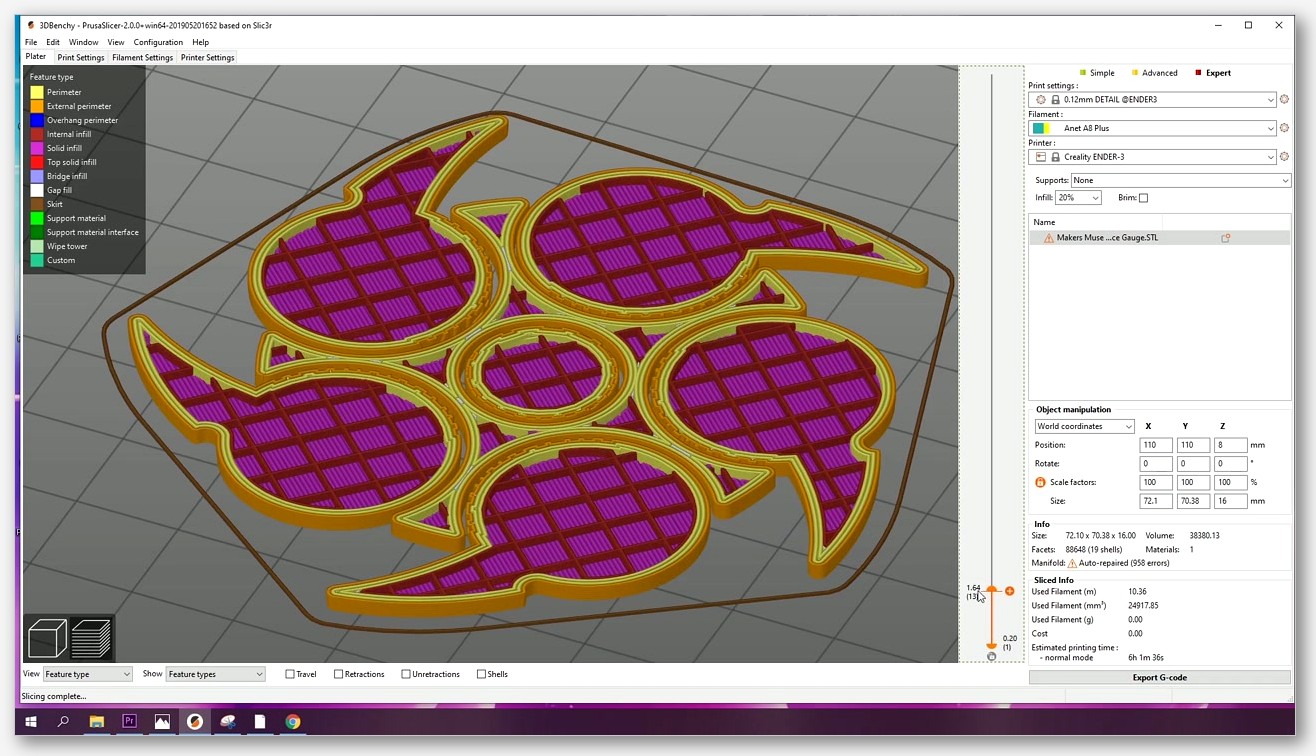
There are three legitimate ways to address it, and they don’t all live inside the slicer. You can shrink the first layer in software (OrcaSlicer’s compensation setting), you can chamfer the bottom of the model in CAD so the bulge fills the chamfer rather than protruding, and you can dial in your Z-offset and bed temperature so the bulge never forms. A few popular suggestions (brim, raft, auto bed leveling) don’t actually touch the problem. I’ll get to why later.
Why it happens, over-squish meets bed heat
There are two physical causes, and they multiply each other. The mechanical cause is straightforward: if your nozzle is closer to the bed than the configured first-layer height, every extruded line gets squished wider than its set extrusion width. A 0.42 mm line on a 0.4 mm nozzle can spread to 0.55 mm or more if the gap is wrong, and the part comes out measurably oversize at the bottom.
The thermal cause is what makes PETG and ABS so much worse than PLA. A hot bed keeps the bottom layers semi-molten for longer than it takes to print the next few layers above, and the weight of all that subsequent plastic squeezes the soft base outward. Siraya Tech sums it up cleanly in their elephant foot writeup: too much bed heat, a nozzle that’s too close to the build plate, the weight of the print pressing down, and poor cooling at the bottom. Their standard bed temperature ranges line up neatly with how often each material flares:
| Filament | Bed temperature range |
|---|---|
| PLA | 50-60 C |
| PETG | 70-80 C |
| ABS | 80-100 C |
| TPU | 40-50 C |
PLA cools fast enough at 55-60 C that the base sets before the weight of the upper layers can do real damage. PETG and ABS stay tacky for much longer at 70-100 C, so even a slightly low nozzle turns into a visible bulge. That’s why your PLA prints can look perfect on the same printer where your ABS bottoms flare. It isn’t a calibration regression. It’s the material.
Knowing this two-cause model matters because it changes what you reach for first. On PLA, dial Z-offset. On PETG and ABS, you’ll likely need both Z-offset and slicer compensation, because even a perfect nozzle gap can’t fight that much heat soak. The OrcaSlicer calibration guide is the right place to start before touching the compensation slider.
The OrcaSlicer setting: elefant_foot_compensation
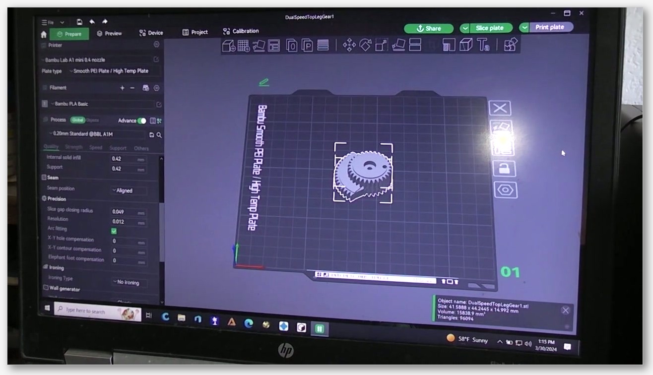
OrcaSlicer’s primary lever for this is a setting called Elephant foot compensation, which lives in the Quality tab under the Precision section. The UI label uses the correct English spelling. The internal config key, however, is elefant_foot_compensation, spelled with one fewer “e” than the English word. That isn’t a typo in this article. It’s a heritage quirk inherited from PrusaSlicer’s source code, and you’ll see it preserved verbatim in OrcaSlicer’s PrintConfig.cpp. If you’re editing JSON profiles or grepping logs, search for “elefant” or you’ll come up empty.
Here are the verbatim particulars from the source:
- Label: Elephant foot compensation
- Default value: 0.0 mm
- Minimum: 0
- Tooltip: “Shrinks the first layer on build plate to compensate for elephant foot effect.”
What it does is shrink the first-layer perimeter inward by the value you set. If you enter 0.15 mm, every outer wall on the first layer is offset 0.15 mm toward the inside, so when that 0.15 mm of bulge forms during printing, the bulged edge lands roughly where the design wall was supposed to be. The 0.0 mm default means no compensation, which makes sense for a generic profile that can’t assume your bed temperature, plate type, or filament.
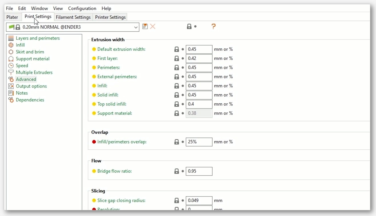
Two important caveats. First, OrcaSlicer didn’t invent this feature. The setting is inherited wholesale from PrusaSlicer, which is why the spelling quirk persists. PrusaSlicer’s knowledge base notes that values around 0.2 mm usually work well for the default 0.4 mm nozzle, and that official Prusa profiles have this setting turned on by default. OrcaSlicer’s default is 0.0 mm; Bambu’s stock profiles override that for some printers, which I’ll get to in the per-filament section.
Second, this setting has a known limitation flagged in OrcaSlicer Issue #6871 (open as of writing). If the bottom of your part has a chamfer or radius so the second layer overhangs the first, aggressive compensation can shrink the first layer enough that the second layer’s outer line gets printed in the air with nothing under it. That shows up as a stringy, droopy second-layer edge. For flat-bottomed parts this never bites, but on something like a chess pawn with a curved foot, it’s a real trade-off.
Companion settings: compensation layers and layer density
There are two other settings that sit next to the main compensation field, and most beginners ignore them. They control how the compensation tapers out and what happens to the solid infill on the affected layers.
The first is elefant_foot_compensation_layers. Its defaults from the source:
- Label: Elephant foot compensation layers
- Default value: 1
- Minimum: 1
- Tooltip: “The number of layers on which the elephant foot compensation will be active. The first layer will be shrunk by the elephant foot compensation value, then the next layers will be linearly shrunk less, up to the layer indicated by this value.”
If you set compensation to 0.15 mm and layers to 4, the first layer shrinks by 0.15 mm, the second by 0.11 mm, the third by 0.08 mm, the fourth by 0.04 mm, and from layer five onward the geometry matches the design exactly. That linear taper smooths the transition from the inset first layer back to full size, which matters because a sharp single-layer step can be visible on shiny PETG. The default of 1 only shrinks the first layer, which works fine on matte PLA but often leaves a visible step on glossy materials.
The second is elefant_foot_layers_density:
- Label: Elephant foot layers density
- Default value: 100%
- Range: 50-100%
- Tooltip: “Density of internal solid infill for Elephant foot layers compensation. The initial value for the second layer is set. Subsequent layers become linearly denser by the height specified in elefant_foot_compensation_layers.”
This one’s less obvious. When you compensate the first layer, the solid infill on the layer above can end up with excess material because it’s filling a slightly larger area than the layer below. That excess shows up as ripples or nozzle-scrape marks. Dropping the layer density to around 80-90% on the second layer (with subsequent layers ramping back up linearly) gives the extra material room to spread without piling up. OrcaSlicer’s wiki suggests starting at 80-90% density with 1-2 compensation layers, then tuning based on visible ripples.
My starting point on most filaments is 2 compensation layers and 90% density. Enough taper to hide the step on glossy PETG, enough density reduction to avoid ripples without weakening the part.
Per-filament starting values (community ranges)
I have to be careful here, because the honest answer is that no authoritative “use 0.15 mm for PETG” number is published anywhere. The values floating around forums are community averages compiled from user reports, and they’re fine as starting points, not gospel.
The one number with a primary source: per OrcaSlicer Issue #2239, the stock Bambu Lab 0.4 mm P1S PLA profile ships with elephant foot compensation set to 0.15 mm. The 0.6 mm nozzle profile for the same printer is set to 0. That’s the only verified profile value I’ll put my name on. Everything else below is community-reported starting points, not OrcaSlicer defaults:
| Filament | Starting compensation (community) | Notes |
|---|---|---|
| PLA | 0.10-0.15 mm | Matches Bambu P1S PLA stock 0.15 mm (Issue #2239) |
| PETG | 0.15-0.20 mm | Stays soft longer at 70-80 C bed; expect more bulge |
| ABS | 0.20-0.25 mm | Worst offender at 80-100 C bed temperatures |
| TPU | 0 mm typical | TPU doesn’t tend to flare, but unverified per-printer |
I tune from these numbers in 0.05 mm increments. Print a 25 mm calibration cube, measure the base and the upper section with calipers, and adjust by the difference divided by two (since the bulge is on both sides of any wall). On my own printer I’ve landed on 0.12 mm for matte PLA, 0.18 mm for translucent PETG, and 0.22 mm for black ABS. Yours will differ depending on plate type, bed temperature, and slicer-profile flow.
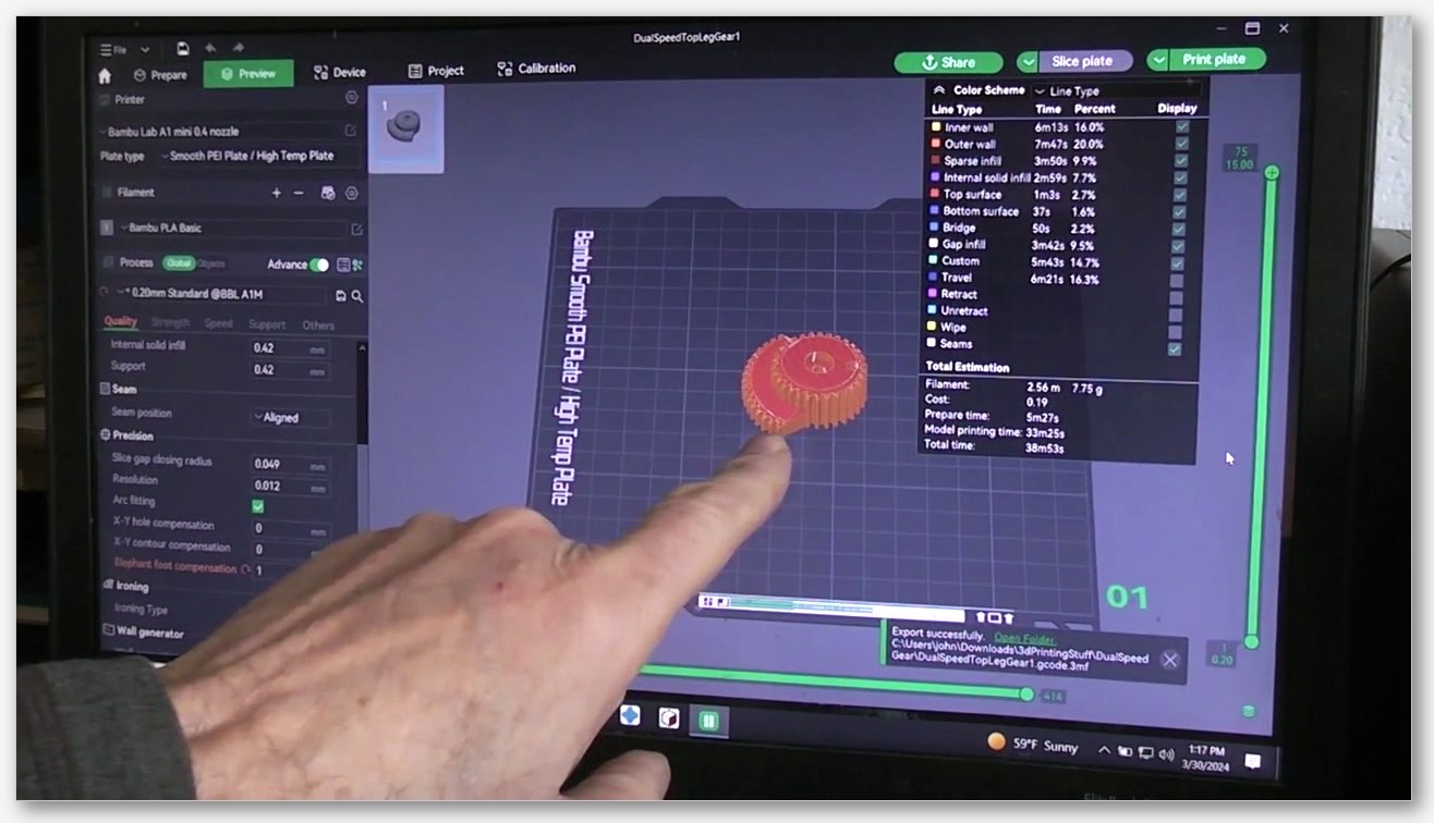
One more caveat. OrcaSlicer Issue #9069 (open) raises a related point: the appropriate compensation depends on the build plate type, but the current setting doesn’t auto-adjust when you switch plates. Bounce between a textured PEI cool plate and a smooth high-temp plate, and you’ll need to retune per plate.
First-layer flow vs walls: the bottom_solid_infill_flow_ratio trap
If you’ve spent any time on Reddit threads about elephant foot, you’ve probably seen someone confidently recommend dropping the “bottom surface flow ratio” or “first layer flow” to shrink the bulge. I tried this, watched my first-layer adhesion fall apart, and then went hunting for what the setting actually does.
OrcaSlicer Issue #11838 (closed 1 March 2026) settled it. Reporter VaLLDaR opened the ticket expecting bottom surface flow ratio to affect all first-layer lines. The verbatim body text: “Walls flow rate not affected at all. Only first layer infil flow rate changes.” So bottom_solid_infill_flow_ratio only modulates first-layer solid infill flow, not the wall perimeters. Since elephant foot is a wall-perimeter defect, this setting can’t fix it. Lower the flow and you’ll just starve the first-layer floor.
This isn’t a bug. It’s working as designed. Ignore any advice that tells you to lower bottom flow to fix elephant foot. Wall perimeter flow is a different setting entirely, and dialing it down will give you weak walls and poor layer adhesion.
Z-offset and ABL: why ABL is not a fix
Before you compensate anything in software, get the Z-offset right. If your nozzle is squishing the first layer too hard, no amount of slicer compensation will hide that consistently, because the physical bulge will scale with your error.
Standard Siraya Tech advice is to bump Z-offset up by 0.05 mm at a time until the first layer goes from glossy and mashed-looking to matte with visible line texture but no gaps. On a Bambu, that’s the Z-offset slider in device settings. On a Klipper machine, it’s SAVE_CONFIG after Z_OFFSET_APPLY_PROBE. There’s no universal target value because it depends on probe type, nozzle wear, and plate flatness.
What I see misunderstood constantly is the role of auto bed leveling (ABL). ABL probes the bed at a grid of points and compensates for bed tilt, so a slightly low corner gets the same first-layer thickness as a slightly high one. What ABL does not do is set the correct Z-offset for the whole print. If your nominal Z-offset is 0.05 mm too low, ABL will faithfully maintain that too-low gap across the entire bed, and you’ll get uniform elephant foot everywhere instead of in one corner. ABL is necessary on a tilted bed; it isn’t sufficient on a printer with a wrong Z-offset. Treat them as independent calibrations.
If your machine has bed leveling but you’ve never explicitly set Z-offset, that’s almost always the first thing worth fixing. The first-layer problems guide walks the full diagnostic if you want to rule out other causes.
The CAD chamfer-bottom alternative
This is my favorite trick because it works without any slicer tuning, and once you’ve designed a part with a bottom chamfer you can print it on any machine in any material and get a clean base.
The idea: add a small 45-degree chamfer along the bottom edge of your model in CAD. Siraya Tech’s guide recommends 0.5 to 1 mm; Creality’s guidance suggests a small chamfer or fillet around 0.5 to 5 mm at 45 degrees. The mechanism is simple: when the elephant-foot bulge forms, it fills the chamfer rather than protruding past the design surface. Looked at from the side, the part appears to have a perfectly sharp 90-degree base edge, because the bulge stops at the top of the chamfer.

I default to a 0.6 mm chamfer at 45 degrees on any functional part where the bottom edge is visible. It costs no slicer setup, no per-filament tuning, and no risk of the Issue #6871 unsupported-second-layer problem. The downsides: you have to own the source CAD (you can’t easily chamfer a downloaded STL without messy mesh work), and a chamfer adds a slight overhang at the very first layer. For most desktop FDM machines, 0.5-1 mm at 45 degrees is well within capability.
If you split your time between functional parts and display parts, lean on slicer compensation for the former and the chamfer trick for the latter.
Why brim, raft, and skirt don’t fix it
This is the myth-busting section, and I’m going to be blunt because the bad advice is everywhere. Brim, raft, and skirt do not fix elephant foot. They address adhesion problems, which is a different category of defect.
A brim is a single-layer ring of extra perimeters printed on the build plate around the model. Its job is to give the part more first-layer surface area so it doesn’t lift or warp. It doesn’t change the geometry of the part itself, so the bulge still forms exactly as before. Worse, if you’ve set compensation aggressively and then add a brim, the inset first layer can leave a visible gap between the brim and the part, making it hard to peel cleanly. PrusaSlicer’s KB notes this directly: if your brim doesn’t connect properly, you likely have elephant foot compensation set too high. The same conflict is the entire subject of PrusaSlicer Issue #6389, titled “Elephant foot compensation makes Brim useless (first lay adhesion wise).”
A raft is a thicker, multi-layer printed platform between the bed and the part. It can actually make elephant foot worse because the raft itself develops its own bulge, and the first part layers sit on a slightly uneven surface. Rafts help when you can’t get any first-layer adhesion at all, but they’re not an elephant foot fix.
A skirt is just a few outline rings printed near the model to prime the nozzle. It does nothing to the part at all. The brim, raft, and skirt guide covers when each actually helps. For elephant foot specifically, none of them are the answer.
Troubleshooting checklist and FAQ
Here’s the order I work in when a part shows elephant foot, from cheapest-to-fix to most-involved. Don’t skip steps; you’ll waste time chasing the wrong cause.
- Check Z-offset. Print a single-layer square or a first-layer test pattern. If lines are mashed glossy together with no visible texture, raise Z-offset by 0.05 mm and retry. Repeat until lines have visible texture but no gaps. This alone solves elephant foot on a lot of PLA prints.
- Check bed temperature. If you’re running PETG above 80 C or ABS above 100 C, try the low end of the range first. Hotter beds aren’t always better; on a heavily textured PEI plate, you can often go 5-10 C below the filament spec and still get great adhesion.
- Set
elefant_foot_compensation. Start at the community range for your material (0.10-0.15 mm PLA, 0.15-0.20 mm PETG, 0.20-0.25 mm ABS). Measure with calipers and adjust in 0.05 mm steps. - Tune
elefant_foot_compensation_layersand density. If you can see a sharp step from compensated to non-compensated layers, raise layers to 2-3 and drop density to 80-90% to smooth the transition. - Consider a CAD chamfer. If you own the model, a 0.5-1 mm chamfer at 45 degrees on the bottom edge eliminates the visible defect without any slicer tuning. This is the most robust fix when you have CAD access.
- Check for Issue #6871. If your model has a curved or chamfered bottom and your second layer looks stringy or droopy, your compensation might be too aggressive for the geometry. Lower it or remove the bottom chamfer from the model.
For broader print-quality diagnostics, the wider OrcaSlicer troubleshooting hub covers symptoms from layer shifts to stringing. If you’re specifically working through PETG quirks (and elephant foot is one of many), the PETG settings guide has a full profile walkthrough.
FAQ
What’s the spelling of the OrcaSlicer config key, “elefant” or “elephant”?
The internal config key is elefant_foot_compensation, spelled with one fewer “e” than the English word. The UI label uses the correct English spelling, “Elephant foot compensation.” This is a heritage quirk inherited from PrusaSlicer’s source code. If you’re searching JSON profiles or config files, use “elefant” or you’ll miss it.
What’s the default value in OrcaSlicer?
0.0 mm. The default does nothing. Some Bambu Lab printer profiles override this with a printer-specific value (the 0.4 mm P1S PLA profile ships at 0.15 mm), but that’s a profile-level override, not OrcaSlicer’s default.
Will adding a brim fix elephant foot?
No. A brim is an adhesion aid, not a geometry fix. The bulge forms underneath the part regardless of whether a brim is present. If you’ve set high compensation, a brim can also leave a visible gap between itself and the part. See PrusaSlicer Issue #6389 for the formal report on this interaction.
Will lowering bottom_solid_infill_flow_ratio fix it?
No. OrcaSlicer Issue #11838 (closed 1 March 2026) confirmed this setting only affects first-layer solid infill flow, not wall perimeters. Since elephant foot is a wall-perimeter bulge, this setting can’t address it. Lowering it just starves your first-layer floor of plastic.
Does my printer’s auto bed leveling fix elephant foot?
No. ABL corrects for bed tilt across the build surface; it doesn’t replace a correct Z-offset. If your Z-offset is too low, ABL will maintain that too-low gap uniformly across the bed and you’ll get elephant foot everywhere instead of in one corner.
How many compensation layers should I use?
The OrcaSlicer default is 1. Most users find 1-2 works on matte PLA and 2-3 helps hide the transition on glossy PETG. The OrcaSlicer wiki suggests starting at 1-2 layers with 80-90% density and tuning from there.
I’m on a Bambu P1S, do I need to change anything?
The stock 0.4 mm nozzle PLA profile ships at 0.15 mm compensation, which is a sensible starting point. On PETG and ABS you’ll want to test and likely raise the value. The 0.6 mm nozzle profile ships at 0 and may need tuning.
Elephant foot looks intimidating until you understand the two-cause model behind it. Get Z-offset right, pick a sensible bed temperature, set compensation to a community-ranged starting value, and tune from calipers. If you own the CAD, a 0.5-1 mm bottom chamfer beats every slicer fix for visible parts. Skip the brim-as-fix advice, ignore lower-bottom-flow advice for this, and don’t expect ABL to do Z-offset’s job. For everything else that goes wrong in the first few layers, the first-layer problems guide picks up where this one leaves off.
Related OrcaSlicer guides
- OrcaSlicer Troubleshooting: Master Index of Every Common Fix
- OrcaSlicer Print Stops Mid-Print: Causes and Recovery Guide
- OrcaSlicer Print Time Estimate Wrong: Why and How to Fix
- OrcaSlicer Crashing While Slicing? 8 Fixes for E-Cores, GPU, RAM
- OrcaSlicer Max Volumetric Speed Test: Find Your Hot End Limit (2026)