
The first time I noticed VFAs on a print, I thought my nozzle was clogging. I was running a tall vase in PETG on a Bambu P1S, raking light hitting it sideways on the workbench, and the whole front face looked like someone had brushed fine corduroy onto the plastic. Tiny parallel stripes, perfectly regular, marching up the wall every two millimetres or so. The dimensional accuracy was fine. The corners were sharp. But that surface ruined what should have been a showpiece print.
I spent the next three evenings chasing it. I dropped the outer wall speed. I bumped it back up. I re-ran the input shaper auto-cal. I rechecked the belt with the guitar-tuner app I keep on my phone. Nothing on the slicer side moved the needle, and I started to suspect I was looking at a hardware problem masquerading as a slicer one. That’s when I finally sat down and ran the OrcaSlicer VFA test the way it’s meant to be run, with a calibration order behind it and a plan for reading the tower. This guide is what I wish I’d had on the bench that week.
I’ll walk you through what VFA actually means inside OrcaSlicer 2.3.x, how the test prints and what each band on the tower really represents, a decision tree for telling ringing apart from belt-meshing apart from salmon skin, and the honest list of things the slicer can’t fix no matter how clever you get with profile keys. If you’d rather start from the beginning, my OrcaSlicer calibration guide covers the whole pipeline. The VFA test is the last stop on that road.
- What VFA stands for in OrcaSlicer
- What the VFA test actually prints
- The diagnosis decision tree
- Mechanical causes vs slicer causes
- Where VFA fits in the calibration order
- Speeds, accelerations, and the dialog fields
- How to read the printed tower
- Feeding results into Resonance Avoidance
- Per-printer notes (Bambu, Klipper, Marlin)
- Common mistakes that waste a tower
- When the VFA test can’t fix it
- FAQ
What VFA stands for in OrcaSlicer
VFA is short for Vertical Fine Artifacts. The phrase covers a category of surface defect, not a single one, and that distinction matters more than anything else in this article. The Wevolver technical overview and the OrcaSlicer wiki both describe VFAs as microscopic ridges on vertical surfaces, typically ten to forty microns wide, appearing at regular intervals on smooth walls. On GT2 belt systems the spacing often lands right around two millimetres, which happens to match one tooth of belt travel through the pulley.
So when somebody says “I’ve got VFAs,” they could mean ringing. They could mean belt-meshing banding. They could mean salmon skin. They could mean Z-banding from a bent leadscrew, or a layer shift, or even a chronic seam that they didn’t realise was a seam. The OrcaSlicer VFA test is built to separate one of those (speed-dependent resonance) from the rest of them. The other subtypes show up on the tower too, but you fix them in different places.
Inside OrcaSlicer 2.3.x the test lives at Calibration → More → VFA in the top menu bar. The same path is confirmed on the OrcaSlicer wiki page for VFA, on the Obico walkthrough, and on the orcaslicer.com mirror of the wiki. In 2.3.x the docs sidebar happens to nest VFA under Input Shaping, but the in-app entry point hasn’t moved. You get a dialog with three fields (Start speed, End speed, Step) and a Generate button. That’s it. The slicer builds the tower model on the fly based on the range you typed in.
What the VFA test actually prints
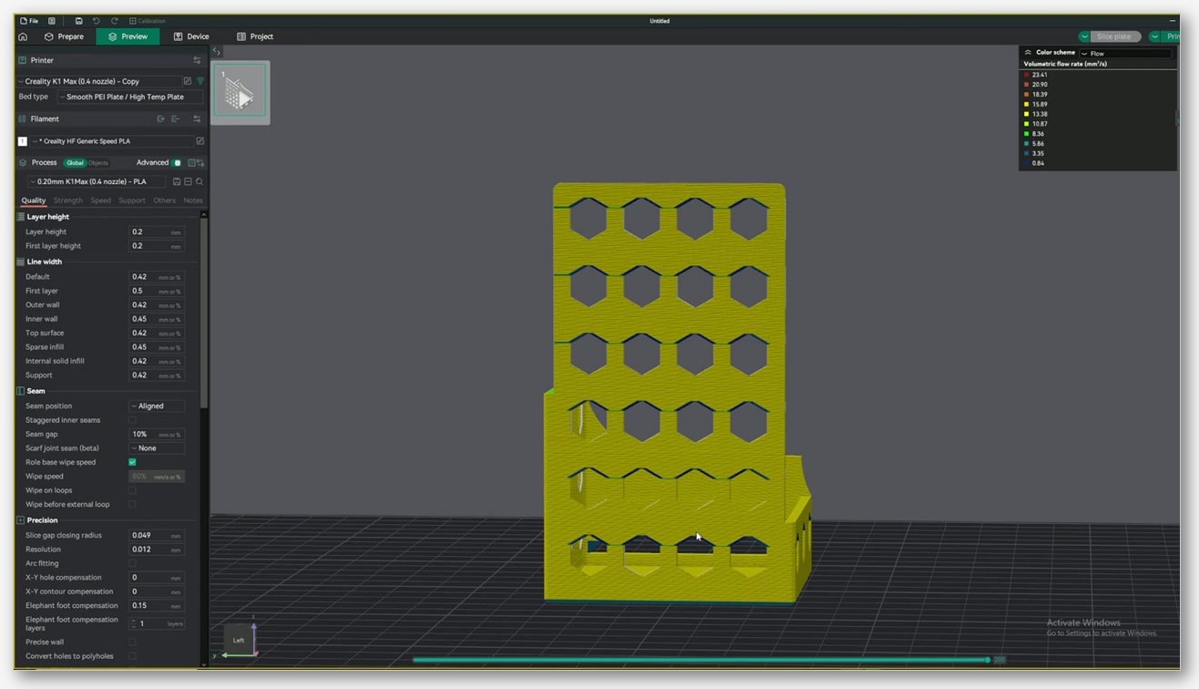
The model OrcaSlicer generates is a tall, hollow tower with thin vertical walls and a stack of hexagonal cutouts running up the front and back faces. The hexagons aren’t decorative. They give you a flat reference patch between each cutout where the outer wall is unbroken, which is exactly where VFAs show up if they’re going to. Each vertical “band” of the tower (the strip from one row of hexagons to the next) is printed at a different outer-wall speed.
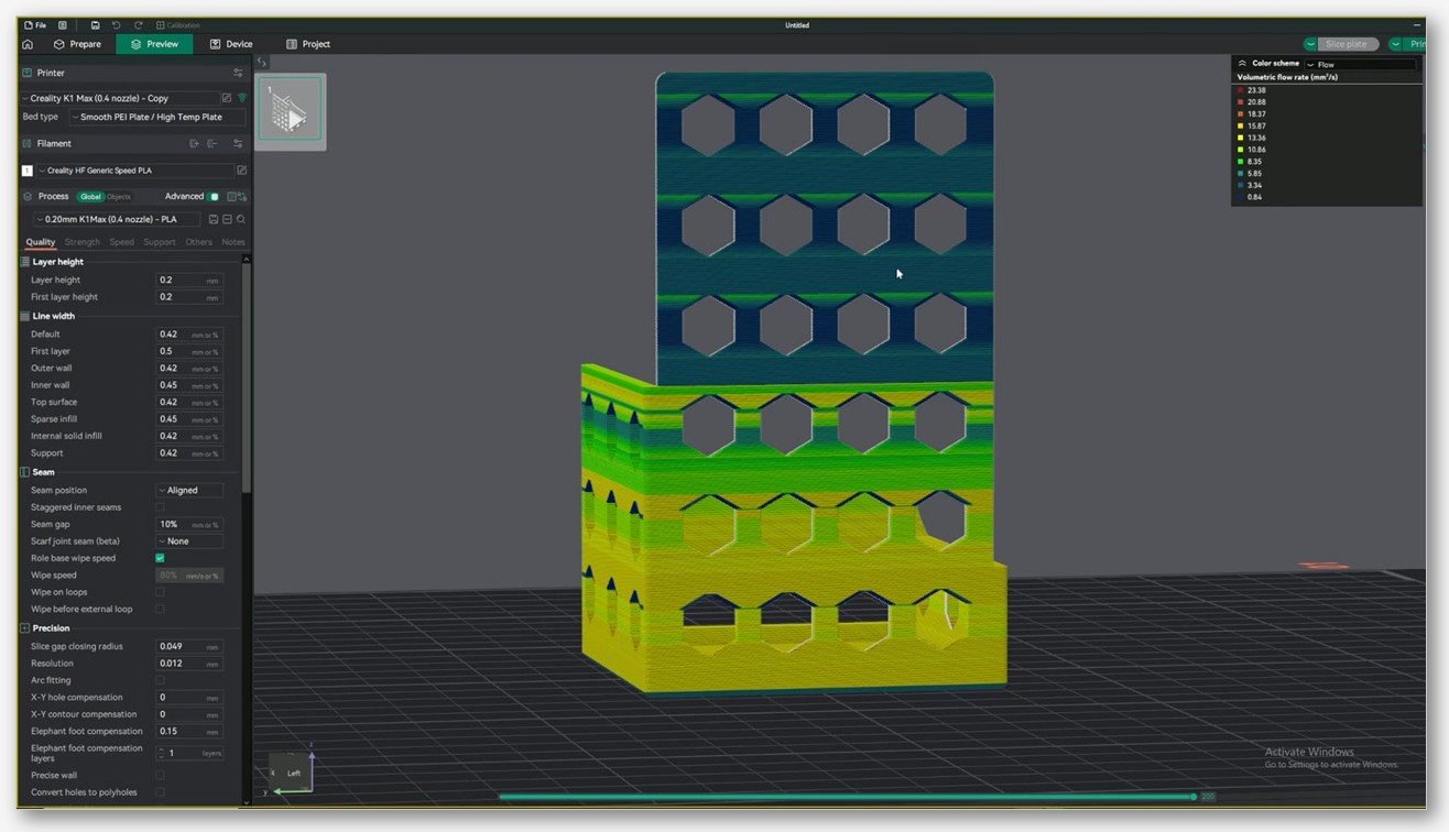
The speed assignment is mechanical. If you typed Start 160, End 500, Step 20, the lowest band prints at 160 mm/s, the next at 180, then 200, and so on up to 500. The Obico guide gives a tidy formula: Speed at notch N = Start + (Step × (N − 1)). You can verify that by hovering over a band in the Preview pane and checking the speed colour-map at top-right.
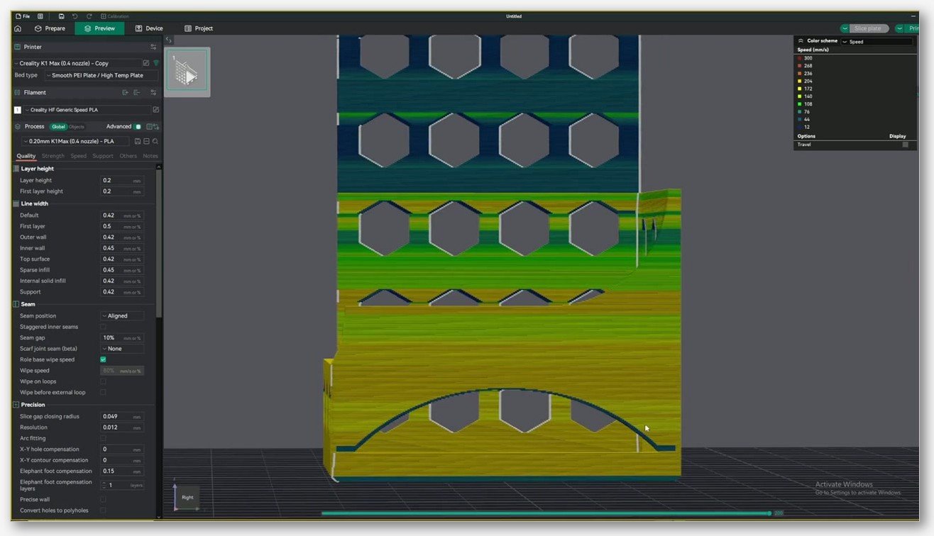
One thing the wiki page is firm about and that I’d repeat twice: there is no shipped default speed range. The temp tower has a 5 °C step baked in. The VFA dialog does not. You have to type your own Start, End, and Step values based on the printer you’re calibrating, and if you skip that thought you’ll either run a tower that’s too coarse to be useful or one that bumps into Max Volumetric Speed halfway up and stops being meaningful. I’ll come back to MVS in the speeds section because it’s the single most common reason a VFA test fails silently.
The diagnosis decision tree
This is the part I find people skipping, which is funny because it’s the part that saves the most filament. Before you generate a tower, look at the print that’s bothering you and decide what kind of artifact you actually have. Different artifacts come from different parts of the printer, and only one of them is what the VFA test fixes.
Here’s the mental model I use on the bench:
- Echo or wavy lines that fade after a corner. That’s classic ringing (sometimes called ghosting). The wavelength tells you the resonant frequency of the axis. It fades because the oscillation damps out as the head moves in a straight line. Fix domain: input shaper, acceleration, and belt tension.
- Even, repeating fine vertical lines spaced about 2 mm across the whole wall, not fading. That’s belt-tooth meshing, sometimes called belt transmission error. Two millimetres is one tooth of GT2 belt pitch travelling through the pulley. It will not go away in software. Fix domain: belt quality, idler tension, pulley grub screws, and in some cases a quality-control problem with the belt itself.
- A diagonal sheen on flat walls, especially right after a seam or short move. That’s salmon skin, driven by pressure advance miscalibration on Klipper and Bambu firmware, or by Linear Advance on Marlin. Fix domain: re-run the pressure advance calibration.
- Horizontal bands at a constant Z spacing. If the spacing matches one full leadscrew rotation (often 2 mm or 4 mm), it’s Z-banding. Bent leadscrew, binding Z, or POM nut wear. Fix domain: hardware.
- A sudden horizontal step in the wall. That’s a layer shift, not a VFA. Belt tension, stepper current, or a decoupled pulley.
- A vertical line down one side of every part. That’s a seam, and it’s a slicer issue. Aligned, Random, or Painted seam settings.
- A rough zone that only shows up above a certain speed. Now we’re talking. That’s speed-dependent resonance, and it’s exactly what the VFA test surfaces.
- Rough on one axis, smooth on the perpendicular face. Axis-specific resonance. Input shaper per axis, or belt tension on the offending axis.
The rule of thumb I keep in my head: ringing fades, true VFAs don’t. If you can run your fingernail down the wall and the texture is exactly the same one centimetre after a corner as it is ten centimetres after a corner, you’re not looking at ringing. You’re looking at a steady-state artifact, and changing your acceleration won’t help.
Mechanical causes vs slicer causes
Once you’ve decided what kind of artifact you have, the next question is whether you can fix it in OrcaSlicer at all. I’ve split this into two honest lists. The first is everything that’s actually in the slicer. The second is everything that lives in the physical printer and will laugh at any profile change you throw at it.
What you can fix in the slicer
- Outer wall speed. Lower it, or enable “Don’t slow down outer walls” so the slicer doesn’t drop into the slow zone where most printers ring.
- Acceleration limits, specifically for outer walls. A separate accel for outer walls is one of OrcaSlicer’s best quality-of-life features.
- Jerk on Marlin, Junction Deviation on Klipper. The cornering calibration walks through this.
- Pressure Advance for Klipper and Bambu firmware, Linear Advance for Marlin.
- Input Shaper frequency and damping, which OrcaSlicer 2.3.x can write into the machine profile for Bambu firmware. I’d cross-reference this with the input shaper guide.
- Resonance Avoidance Speed Range. This is the field you actually fill in after reading the VFA tower.
- Seam placement. Aligned, Random, or Painted.
What requires touching the printer
- Belt tension. The community-standard trick is plucking the belt like a guitar string and using a phone guitar-tuner app to read the frequency. Target frequencies vary wildly by printer family, so check your specific machine’s documentation or community wiki rather than chasing a universal number.
- Idler and pulley grub-screw tightness. A pulley that’s slipping a thousandth of a millimetre per move creates the most maddening intermittent VFAs you’ll ever see, and no slicer fix touches them.
- Frame rigidity. I once chased VFAs for a week and finally figured out my desk had a slight wobble in the leg. Moved the printer to a concrete slab, VFAs gone.
- Bed levelness. Uneven first-layer pressure cascades upward into wall artifacts later in the print.
- Leadscrew straightness and Z-axis play. POM nuts wear, leadscrews bend, couplers slip.
- Linear rail or rod lubrication. Dry bearings produce stick-slip motion, which prints as banding.
- Stepper resolution. Wevolver covers 0.9° stepper upgrades as a fix for printers with chronic 1.8° step ripple on the X or Y axis.
The diagnostic shortcut I lean on: if the rough band shifts position when you change slicer settings, it’s slicer. If it appears at every speed and never moves no matter what you do in OrcaSlicer, it’s mechanical. Run the VFA tower twice with different settings and compare. If the artifacts move, you’ve got something to chase in software. If they don’t, put down the slicer and pick up the Allen keys.
Where VFA fits in the calibration order
The VFA test goes last. Not first, not somewhere in the middle, last. I see this question come up constantly on the OrcaSlicer GitHub discussions (the canonical thread is discussion #2476 on calibration order), and the answer is consistent. Every prior calibration changes the surface of your prints. If you VFA-test before you’ve nailed flow rate and pressure advance, you’re reading a tower whose results will shift the moment you fix the upstream stuff.
The order I run, in plain English:
- Temperature tower. Establish the viscosity baseline. Everything else assumes you’ve found a temperature where your filament extrudes consistently.
- Flow rate calibration. Get the extrusion volume right. Pressure advance can’t compensate for a flow value that’s 10% off.
- Pressure advance. The corner and pressure response. This has to come after flow rate.
- Retraction. Kills stringing.
- Max Volumetric Speed. This one is critical for the VFA test specifically. If your hotend’s MVS is the limiting factor, you’ll never reach the higher speed bands on the tower and your test result is meaningless. I’ll come back to this.
- Cornering (Junction Deviation or jerk, depending on firmware).
- Input shaper. Bambu auto-cal, Klipper SHAPER_CALIBRATE, or a Marlin ringing tower with M593. This kills the broad resonance peaks.
- VFA. The last test. Surfaces whatever resonance peaks input shaping didn’t fully suppress, plus any mechanical VFAs no software will ever fix.
- Tolerance and dimensional accuracy as a final pass.
I’ll say this even more bluntly. If you skip MVS and run VFA first, you’ll see the tower stop responding to speed changes above whatever your hotend can actually push through the nozzle. You’ll think you’ve found “the wall,” and you’ll set a Resonance Avoidance range that’s actually capturing your extruder’s flow limit instead of a real resonance. Don’t do that. Run MVS, see where your filament caps out, then build a VFA tower whose Start and End fit comfortably under that cap.
Speeds, accelerations, and the dialog fields
The dialog asks for three numbers and the choice you make depends entirely on the printer class. I’ll lay out the ranges I’ve actually used.
Bambu and Voron-class CoreXY machines. These can usually push outer walls hard. I start at 100 mm/s and end at 300 mm/s in 20 mm/s steps. That’s 11 bands, a comfortable tower height, and it covers the realistic span of speeds you’d actually use on a real print.
Ender 3 V2, Prusa MK3-class, older bedslingers. Don’t be silly. Start at 30 mm/s and end at 150 mm/s in 10 mm/s steps. Bedslingers carry mass, and asking one to print outer walls at 200 mm/s is asking for trouble that no slicer setting will rescue.
Modern CoreXY pushed for speed. 160 mm/s to 500 mm/s in 20 mm/s steps is the Obico-recommended starting range, and it makes sense for K1, K2, X1C with the high-speed profile, P1S in fast mode, and similar machines. Just check MVS first.
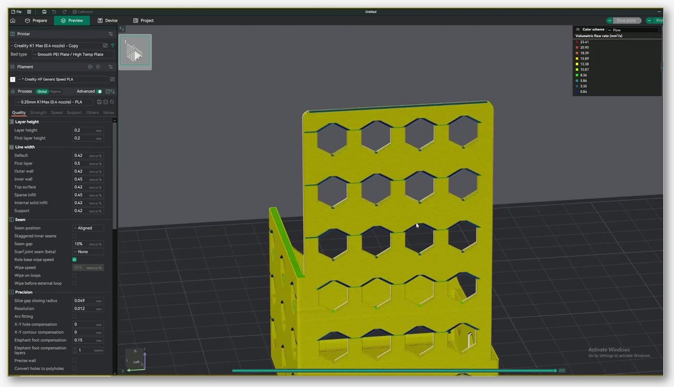
On the step granularity question, finer steps give better resolution but a taller and slower print. I find 10 to 15 bands is the sweet spot. Twenty bands starts to be a lot of plastic. If the first run shows a problem zone between, say, 200 and 240 mm/s, re-run with Start 200, End 240, Step 5 to nail down the exact speed. Two iterations is faster than one giant tower.
The MVS warning, quoted from the OrcaSlicer wiki: “Check that Max Volumetric Speed is not limiting your speeds for this material. If it is, use a higher Volumetric Speed material or recreate the test with a lower max speed.” I’d add to that: with a 0.4 mm nozzle and a 0.2 mm layer height, a 0.42 mm line width, generic PLA at roughly 14-18 mm³/s MVS, you start running into the flow ceiling at about 160-180 mm/s on outer walls. If you want to test higher speeds honestly, you need a high-flow nozzle (a CHT-style nozzle, a Bambu hot end with the high-flow option, or a Mosquito-style hotend) and a high-speed PLA filament rated for higher volumetric flow.
Acceleration is the variable I’d recommend you do not sweep on the same tower. The tower uses whatever acceleration value is set in your active filament and process profile, and it stays constant for the whole print. If you want a two-dimensional speed-times-acceleration map, run multiple VFA towers, one per acceleration value, and label the plates so you don’t mix them up.
How to read the printed tower
Once the tower’s off the plate, give it five minutes to fully cool. Don’t try to read PETG straight off the bed because the surface is still pliable and the reading will lie to you.
Hold the tower under a raking light. I use a desk lamp angled almost horizontal, with the tower flat on the bench, so the light grazes the wall. Any vertical ridge throws a shadow you can see from across the room. Then run your fingernail down each band, top to bottom, on every face.
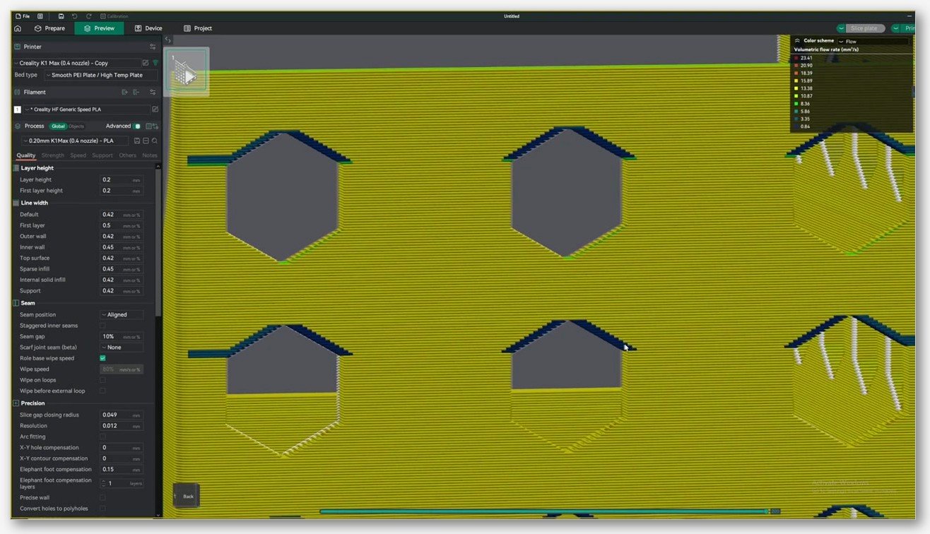
What you’re grading for, band by band:
- Glassy and smooth. No ridges, no audible whirring under your nail. That’s a safe speed.
- Vertical fine ripples. Faint, parallel, often only visible at a glancing angle. That’s a problem speed.
- Audible rough zone. Your nail catches and chatters. That’s the centre of the resonance peak.
- One face fine, the perpendicular face rough. Axis-specific. The rough one is the axis with the problem, and that axis needs input shaper attention or belt-tension work, not a Resonance Avoidance band.
I write the band numbers on a piece of masking tape and stick the tape to the back of the tower. For each band I note: smooth, mild ripple, rough, very rough. Then I do the maths to convert band numbers to speeds using Start + Step times (N minus 1), and I now have a list of speed ranges to avoid. That list becomes the Resonance Avoidance entries.
Two reading mistakes I see often. First, people inspect only one face of the tower. The four flat faces correspond to four different head-direction combinations, and on a CoreXY the X and Y motion are blended into every wall, so the artifact pattern can differ face to face. Look at all four. Second, people grade with overhead lighting, which washes out the surface texture. Use raking light or you’ll miss the mild bands entirely.
Feeding results into Resonance Avoidance
This is where the test pays off, and it’s also where I keep seeing misunderstanding. The VFA test does not auto-save the results into the profile. There’s no clever button. You read the tower by eye and you type the ranges into the printer profile yourself.
The setting lives at Printer settings → Motion ability, with the Advanced toggle on. You’ll see fields for Resonance Avoidance Speed Range, and you enter the start and end of each problem-speed window. OrcaSlicer’s slicer engine then plans outer-wall toolpaths that skip those speed bands. If you found that 220 to 260 mm/s is rough, you tell the profile to avoid 220-260, and the slicer either drops below 220 or jumps above 260 for outer walls. No more rough zone.
This feature wasn’t always in OrcaSlicer. It was ported in from QIDI Studio in 2024 after GitHub issue #7120, and the XDA Developers writeup remains the best layperson explanation of what it does and why it matters. Resonance Avoidance and input shaping are complementary, not redundant. Input shaping flattens the resonance peaks at the motion-planning level. Resonance Avoidance routes the toolpath around whatever bumps the shaper didn’t fully kill. You can and should use both.
What I would not do: enter a huge avoidance window like 100-400 mm/s “just in case.” That defeats the whole point. The slicer will end up cornering toolpaths into weird speed compromises, and the print quality can actually get worse. Be surgical. If the rough zone is 30 mm/s wide, the avoidance entry should be about 30 mm/s wide.
Per-printer notes
Bambu Lab (X1C, P1S, P1P, A1, A1 mini, H2D, H2C, P2S)
Bambu firmware auto-calibrates input shaper on boot or on demand from the device. You don’t run SHAPER_CALIBRATE manually. By the time you’re at the VFA stage, the broad resonance peaks should already be handled. What remains is the narrow stuff, and it often shows up at lower speeds rather than higher ones.
The advice you’ll see again and again on the Bambu Lab forum (threads like Persistent 2mm VFAs on X-axis and Possible Fix for Ghosting / VFA Artifacts) is “print outer walls faster.” Often that works. Bumping outer-wall speed from 80 mm/s to 120 mm/s, or all the way up to 200+ mm/s, can push the head past a low-frequency resonance band and clean up the wall. The “Don’t slow down outer walls” toggle in OrcaSlicer accomplishes much of the same thing without you having to manually pick a single speed for every perimeter.
I’d flag this honestly though: “print faster” is sometimes a cop-out. The persistent 2 mm VFA threads on Bambu’s forum keep coming back to belt-tension and pulley issues, and no amount of slicer tweaking fixes those. If you’ve got a P2S or an H2C and the wall artifacts are independent of speed, look at the hardware. The community reports on those two models trend toward belt-related root causes rather than slicer-side ones.
Klipper-based printers (Voron, RatRig, Sovol SV08, Prusa MK4 in Klipper mode)
Run SHAPER_CALIBRATE first. With an ADXL345, LIS2DW, LIS3DH, or MPU-9250 accelerometer mounted on the toolhead, Klipper sweeps each axis, picks an optimal shaper type (MZV, EI, ZV, 2HUMP_EI), and writes recommended frequencies into printer.cfg. The Klipper Resonance Compensation docs are the canonical reference here, and the Measuring Resonances page covers the accelerometer wiring.
MZV is the most common shaper choice and a solid default for Cartesian and CoreXY. EI and 2HUMP_EI are used on Deltas and on machines with broadly-spaced resonance peaks. After auto-cal, run the OrcaSlicer VFA test to see what speed bands still produce ripples, and feed those into Resonance Avoidance. Klipper users have a fallback if they don’t own an accelerometer: print a ringing tower with Klipper’s TUNING_TOWER macro sweeping shaper_freq from 40 to 60 Hz, measure the ridges, and set the shaper frequency manually. The Teaching Tech calibration site walks through the eyeball method.
Marlin without input shaping
You don’t have software resonance compensation. Your levers are mechanical and slicer-config: lower acceleration on outer walls (500 to 1500 mm/s² is a sane band for ghosting-prone machines), low jerk (5 to 10 mm/s), tight belts, and a slower outer-wall speed (40 to 60 mm/s is realistic on an Ender-class machine).
The VFA test still works for you. You just have less to fall back on after reading the tower. Resonance Avoidance is in the slicer regardless of firmware, so you can still enter problem speeds. But the broad peaks you’d kill with input shaping on a modern printer are still going to be there, and your safe-speed window will be narrower.
Marlin with input shaping (M593)
Modern Marlin builds (2.1.x and later) expose M593 for input shaping. The workflow is: print a ringing tower, measure the wavelength of the ripples, convert to Hertz using the tower’s documented speed-to-frequency relationship, then set M593 X F<freq> and M593 Y F<freq> per axis. After that, run the OrcaSlicer VFA test as a verification pass. Ender 3 V2, V3, and similar machines benefit a lot from this if you’ve got the firmware updated.
Common mistakes that waste a tower
I’ve burned filament on every one of these at some point. Save yourself the trip.
- Running VFA before MVS. Already covered, but it’s mistake number one. If your speed range bumps into the hotend’s flow ceiling, the upper bands are flow-limited, not resonance-limited, and you’ll misread the tower.
- Setting the Step too coarse. A 50 mm/s step on a 100 mm/s range only gives you three bands, and the rough zone (if there is one) will probably hide between bands. Use 10 to 20 mm/s steps on a first pass, then iterate finer on the suspect zone.
- Skipping pressure advance first. If your PA is off, every band will have salmon-skin texture on top of any VFA ripples, and you won’t be able to tell them apart.
- Reading the tower with overhead lighting. The fine ripples literally don’t show up. Use a desk lamp angled flat to the bench.
- Grading only one face. Different faces show different artifact patterns because the head’s motion components differ. Read all four.
- Trusting a tower that printed during a stringy session. If your retraction was bad and you’ve got stringing inside the walls, you can mistake retract artifacts for VFAs. Get the retraction calibration done first.
- Setting a huge Resonance Avoidance window because you weren’t sure. Discussed earlier. Be specific, not paranoid.
- Expecting the slicer to save the tower results. It doesn’t. You write them down. The slicer doesn’t know what your eyes saw.
- Running VFA on a cold printer. Print quality changes meaningfully in the first 15 to 30 minutes as the frame and bed equalise temperature. Print a small warm-up object first or just let the bed heat-soak for 20 minutes.
- Using whatever filament was loaded. If you’re going to make decisions about a printer’s behaviour, use a filament you’ve already calibrated end to end. A fresh roll of unknown PLA can produce artifacts that have nothing to do with the printer’s resonance.
When the VFA test can’t fix it
This is the section I wish more articles included, because the honest answer is that the OrcaSlicer VFA test fixes one specific thing: speed-dependent resonance on the outer wall that survives whatever input shaping you’ve already done. It does not fix:
- Belt-tooth meshing artifacts. If the spacing on your wall is around 2 mm and it shows up at every speed, the belt is the problem. Replace it with a high-quality GT2 belt, check the idler bearings for play, and tighten the grub screws on the pulleys.
- Z-banding from leadscrew issues. The fix is mechanical: a straighter leadscrew, a working anti-backlash nut, or in some cases a switch to ballscrews if you’re a Voron person who wants the upgrade.
- Frame flex on a flimsy bench. Move the printer to something rigid. Tile it on a concrete patio if you have to. I’ve seen this on shared desks and on rolling carts.
- Stepper resolution limits. 1.8° steppers driven at high microstepping still have step ripple, and on Y-axis bedslingers this becomes visible at low outer-wall speeds. 0.9° steppers reduce that ripple substantially, though they’re a hardware change and they cost money.
- Worn linear bearings or dry rods. Stick-slip motion prints as banding. Cleaning and lubricating the rods often clears it up.
- Anything related to the seam. Seam artifacts show up regardless of speed, and OrcaSlicer’s seam-placement modes are the lever you reach for.
The Prusa Core One community has had a long-running debate about VFA root causes on the VFA thread on the Prusa forum, which is one of the most thorough public discussions of VFAs on a current-generation printer. Belt tension was the first suspect, but users who tensioned belts to the recommended frequency still saw artifacts. The conversation has since moved toward motor-shaft runout and drivetrain factors rather than a single mechanical culprit, which is a useful reminder that VFA diagnosis is rarely a one-cause story.
It’s worth saying out loud: a perfectly tuned slicer profile cannot rescue a printer that’s mechanically out of spec. That’s not a slicer flaw. It’s just physics. If you’ve run the VFA test, fed the avoid-ranges into Resonance Avoidance, and the wall is still rough, the answer isn’t another profile tweak. It’s an Allen key.
FAQ
Does the OrcaSlicer VFA test save its results automatically?
No. The test produces a printed tower. You read the tower by eye under a raking light, write down the speed bands that showed ripples, and manually type those ranges into Resonance Avoidance under Printer settings → Motion ability. The slicer doesn’t see your eyes.
How long does the VFA tower take to print?
It depends on the speed range you picked, but a 10-band tower at typical CoreXY speeds usually finishes in 45 minutes to an hour and a half. A bedslinger with a 30-150 mm/s range will run longer, often two to three hours. Plan accordingly. If you’re iterating to nail down a specific suspect zone, your second tower can be much shorter because you’ve narrowed the speed range.
Should I run the VFA test on every filament I use?
You don’t have to. The test characterises the printer’s mechanical resonance, which is mostly filament-independent. What does change per filament is MVS, so if you’re switching from generic PLA to a high-flow PLA or to PETG, you might find your safe-speed band is now narrower because of viscosity rather than resonance. I run VFA once after major hardware changes and trust the result across filament types, while keeping an eye on flow-related limitations.
What’s the difference between input shaper and Resonance Avoidance?
Input shaper modifies the motion plan so the head produces less excitation at the printer’s resonant frequency. It flattens the peaks. Resonance Avoidance is a slicer-level feature that routes the toolpath around speed bands where the printer still rings even after input shaping. Use both. They’re complementary, not redundant.
Why does my Bambu printer have VFAs even though the firmware auto-calibrates input shaper?
A few reasons. The auto-cal handles the dominant peak well but doesn’t always catch narrow secondary peaks. Belt-tooth meshing isn’t a resonance problem and input shaping doesn’t touch it. And mechanical issues (loose pulleys, worn idlers, a flexed frame) show up as VFAs regardless of how good the firmware’s shaper is. Run the VFA test, then if the artifacts persist independent of speed, check belts and pulleys.
Can I run the VFA test on a 0.6 mm or 0.8 mm nozzle?
Yes, and you should adjust the speed range down because the wider line width dramatically raises your volumetric flow at any given speed. A 0.8 mm nozzle at 0.4 mm layer height runs into MVS very quickly. Start lower on the Start speed, and pay attention to the flow colour map in the Preview pane before you slice.
What does “Don’t slow down outer walls” actually do?
It forces OrcaSlicer to print outer walls at the speed you set, regardless of how short the perimeter segment is. Without it, the slicer drops outer-wall speed for very short segments, which can put the head into a resonance band on a small feature. With it, the speed stays constant. The setting is covered well in OrcaSlicer’s own video on the topic, and it’s one of the simplest fixes for VFAs that only appear on small parts.
Closing thoughts and what to do next
If you’ve made it this far, you’ve got the full diagnostic stack for VFAs on an OrcaSlicer-driven printer. The short version is: identify the artifact first (ringing fades, true VFAs don’t), do every upstream calibration before VFA, run the test with a speed range that fits comfortably under your MVS, read the tower under raking light, and feed the problem speed bands into Resonance Avoidance under Motion ability. Then accept the honest truth that some artifacts live in the hardware and no amount of slicer cleverness will move them.
The single biggest improvement most people see isn’t from VFA at all. It’s from doing the input shaper calibration properly first. If you skipped that step or you’re not sure your shaper values are right, that’s the first thing I’d revisit. The OrcaSlicer input shaper guide covers Bambu, Klipper, and Marlin workflows. After that, the cornering calibration handles the corner-specific stuff that often gets confused with VFAs.
If you’re new to OrcaSlicer entirely, the full calibration guide walks the whole pipeline in order, and the per-test articles drill into each step. If you don’t already have OrcaSlicer installed, grab the latest release from the official OrcaSlicer GitHub releases page. That’s the official download. This site (orcaslicer.net) is a third-party content site and we don’t host the installer ourselves.
One last thing. If you find that no slicer setting moves the artifact, don’t keep tweaking. Stop. Pluck the belt. Check the pulleys. Look at the leadscrew. Move the printer to a stiffer surface. The slicer can do a lot, but it cannot fix a printer that’s mechanically wobbling. And honestly, once you’ve done the mechanical work, the slicer settings you already had will probably do the rest of the job on their own. Good luck with the tower. Bring a raking light.
Related OrcaSlicer guides
- The Complete OrcaSlicer Calibration Guide (Order Matters)
- How Often Should You Recalibrate OrcaSlicer? 2026 Maintenance Schedule
- OrcaSlicer Input Shaper Calibration for Klipper (2026 Guide)
- OrcaSlicer Max Volumetric Speed Test: Find Your Hot End Limit (2026)
- OrcaSlicer Warping & Lifting Corners: Fixes That Actually Work (2026)