The first time modifier meshes saved my print was a 3-point ABS bracket that kept snapping at the M4 boss under torque. I didn’t want to print the whole bracket at 80% gyroid because that meant doubling the filament budget and adding 90 minutes per copy, so I dropped a tiny modifier cube around the boss, set sparse infill density to 100 inside that cube, and the rest of the part stayed at 15%. Same STL. Same print job. One file in CAD. That’s the trick modifier meshes pull off, and once you get it you start using them everywhere: hidden infill cores under stress points, per-feature wall counts at hinge knuckles, support enforcers under the tiny overhang the auto-generator missed, negative volumes that carve a wire channel through an enclosure without re-exporting the STL.
This guide walks through every modifier-class object OrcaSlicer supports, what you can actually override inside one, where they break, and the worked examples I keep going back to. I’ve kept the menu labels and submenu wording exactly as they appear in the OrcaSlicer source so you can match what you see on screen instead of hunting for a label that doesn’t exist.
Table of contents
- What a modifier mesh actually is
- The five modifier-class object types in OrcaSlicer
- The six primitive shapes you can drop in
- How to add a modifier, step by step
- Which settings you can actually override
- Negative parts vs Mesh Boolean Difference
- Support blockers and enforcers
- Worked examples I use regularly
- Modifier meshes vs paint-on tools
- Height-banded settings without a Height Range Modifier
- Modifiers with Arachne, and why vase mode breaks
- Troubleshooting checklist
- FAQ
What a modifier mesh actually is
A modifier mesh is a secondary volume you attach to a print object that has one job and one job only: overwrite a chosen set of slicing parameters inside the volume it occupies. The mesh itself doesn’t print as solid plastic. It’s invisible at runtime. What it does is tell the slicer “for any extrusion path that falls inside this region, use these settings instead of the part’s defaults.” Everywhere outside the modifier, the part keeps its normal settings.
If you’ve ever wished you could turn one boss solid without making the whole part solid, or force five walls around a hinge knuckle without paying the wall-count tax across 200 square centimeters of skin, that’s the use case. It saves you from chopping the STL into separate parts in CAD, exporting them as a multi-mesh assembly, importing the assembly, and re-aligning everything. You just stick a cube on the part in the slicer and tell it what to override.
The OrcaSlicer wiki page for the object set puts it plainly: “Each Part can have its own unique settings, such as print parameters, supports, and modifiers.” The override engine itself is inherited from PrusaSlicer’s per-volume system, which inherited it from Slic3r. OrcaSlicer didn’t invent this, but the UI for it is decent and the override category list has grown over the last few releases.
Under the hood, OrcaSlicer recognizes five volume types defined in src/libslic3r/Model.hpp: MODEL_PART, NEGATIVE_VOLUME, PARAMETER_MODIFIER, SUPPORT_BLOCKER, and SUPPORT_ENFORCER. We’ll talk about each one in the section below, but the short version is that “modifier mesh” colloquially covers all five. The right-click menu names them with different labels, and the source code uses different enum values, but the mechanism is the same: a sub-volume nested under a host object in the object list, doing something specific where it sits.
The five modifier-class object types in OrcaSlicer
Right-click any part in the object list and you’ll see these five entries, copied verbatim from src/slic3r/GUI/GUI_Factories.cpp:
- Add part: Adds a solid model part as additional geometry. This is not technically a modifier in the override sense. It prints as plastic. Useful when you want to merge a feature onto the host part without booleaning it in CAD.
- Add negative part: Subtracts volume during slicing. Tells the slicer to skip extrusion inside the negative volume. The host geometry stays untouched in the 3MF; the negative is a runtime instruction.
- Add modifier: Overrides Quality, Strength, and Speed settings inside the volume. This is the classic “modifier mesh” use case.
- Add support blocker: Disables auto-generated supports inside the volume. Use it when you know a steep overhang will print fine and you don’t want the slicer adding columns.
- Add support enforcer: Forces auto-generated supports inside the volume, even on geometry the support engine would normally skip.
The labels look almost identical, which trips up new users. The lowercase “modifier” entry is the only one that actually overrides print parameters. The other four either add geometry, remove geometry, or change support behavior. If you’re trying to override sparse infill density inside a region, you want “Add modifier,” not “Add part.”
There’s also a “Change type” submenu (lowercase t, that’s what the source has) that lets you flip an existing sub-volume between Part, Negative Part, Modifier, Support Blocker, and Support Enforcer. That’s useful when you imported an STL as a regular part and then realized you wanted it to behave as a modifier instead. Right-click the sub-volume, hit “Change type,” pick the role you want.
Issue #2343 (closed October 2023) tracked a historical bug where the “Change type” submenu only appeared on negative-part volumes and was missing from the main right-click menu, leaving users confused: “When adding a part as a ‘negative’ you get the ‘change part type’ menu item to change its type. This should be on the main right click menu. I can’t seem to find it anywhere except the part created ‘negative’.” That’s resolved on current builds, but if you’re on an older version and the submenu’s missing, that’s why.
The six primitive shapes you can drop in
When you pick “Add modifier” (or any of the other four), OrcaSlicer pops a submenu with six built-in primitives. The list, from GUI_Factories.cpp:
- Cube
- Cylinder
- Sphere
- Cone
- Disc
- Torus
That’s the complete list. There’s no “Slab” primitive in OrcaSlicer (PrusaSlicer has one; OrcaSlicer doesn’t), and there’s no “Box” or “Capsule” entry either. If you need a shape that isn’t in the six, you can load any STL by picking “Load…” at the bottom of the same submenu. Most of my use cases are cube or cylinder, because they snap to bounding boxes naturally and you can scale them without distorting the override region.
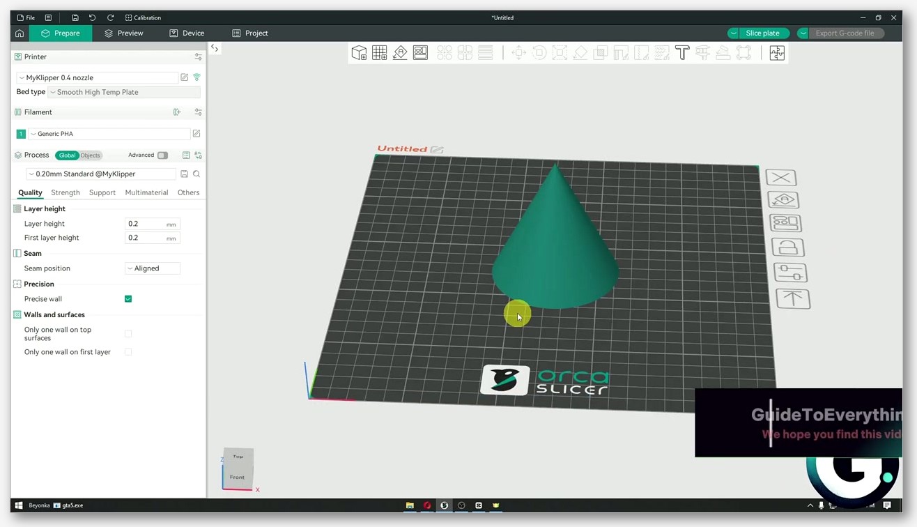
One thing I learned the hard way: the primitive drops in at the center of the host part by default, not where you right-clicked. Use the Move and Scale gizmos on the right toolbar to position and resize it. The Object Manipulation wiki page covers the gizmo workflow if you’re new to it.
How to add a modifier, step by step
Here’s the workflow I use 95% of the time:
- Open your STL in OrcaSlicer. Place it on the bed.
- In the object list (top right panel), right-click the part name. Don’t right-click in the 3D viewport; that gives you a different menu.
- Hover “Add modifier.” The six-primitive submenu appears.
- Pick a primitive that roughly matches the region you want to override. For a screw boss, that’s a cylinder slightly bigger than the boss. For a hinge knuckle, that’s a cube or a torus.
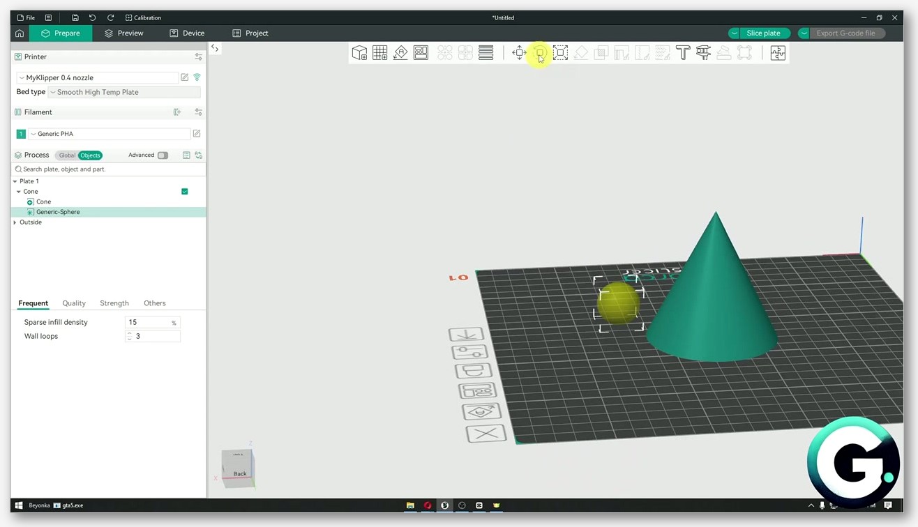
- The modifier appears at the center of the host part with default dimensions. Click it in the object list or in the viewport to select it.
- Use the Move (M), Scale (S), and Rotate (R) gizmos to position the modifier where you actually want it.
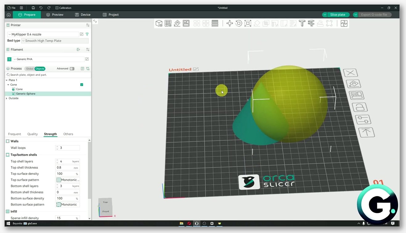
- With the modifier still selected, the right-hand panel switches to a per-modifier override view. Hit the “+” next to a setting (or the “Add settings” button in some builds) to add a parameter override. Pick from Quality / Strength / Speed.
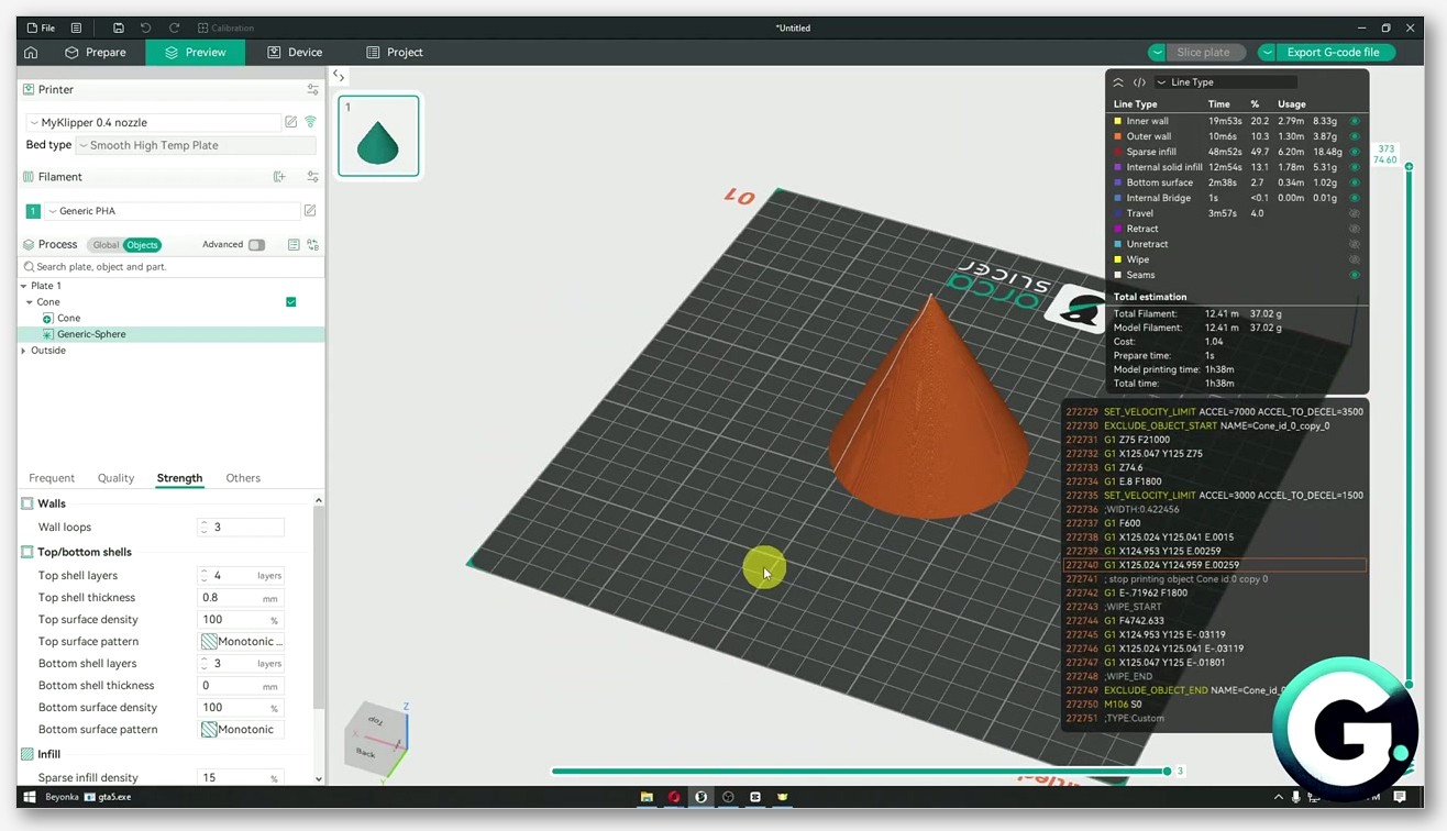
- Set the value. Slice. Check the preview to confirm the override actually landed where you wanted.
If your modifier needs a custom shape that isn’t one of the six primitives, you’ve got two options:
- Load STL as modifier: Right-click the host part, “Add modifier,” then “Load…” at the bottom of the submenu. Pick the STL. It loads as a sub-volume with the modifier role already set.
- Split to Parts: If you authored a multi-mesh STL in CAD where the modifier region is its own mesh, import the whole thing as one object, then right-click and pick “Split to Parts.” The wiki describes it: “When selecting an Object with a single Part that contains multiple meshes, users can choose to split the Object into individual Parts. Each Part will represent a single mesh from the original Object and will allow for independent manipulation and settings.” Once split, right-click each sub-part and use “Change type” to flip it to Modifier.
There’s no top-level “right-click on an object → Convert to Modifier” entry yet. Issue #7588 (open, November 2024) is the open feature request: “Add object to modifier conversion to right click menu… because OrcaSlicer lacks this capability that exists in PrusaSlicer.” For now, you import as part and Change type, or you import via “Add modifier → Load…”. Issue #4302 (closed not planned, March 2024) flagged that “current solution with add modifier from file is problematic due to problem with good positioning,” and that’s still real: the loaded modifier lands at coordinates relative to its own origin, not where you’d expect, so you usually have to reposition.
Which settings you can actually override
This is where new users burn an hour. Not every print setting is overridable per modifier. The source defines PART_CATEGORY_SETTINGS in GUI_Factories.cpp, and that controls what shows up in the override picker when a Modifier or Part volume is selected. Three categories, full stop:
Quality
Includes ironing type, ironing flow, ironing spacing, ironing inset, bridge flow, make overhang printable, bridge density, ironing expansion, and the ZAA (Z anti-aliasing) family. If you want a specific region ironed and the rest of the top surface left alone, this is where you do it.
Strength
The biggest category by far, and the one I use most. Wall loops, top shell layers, top shell thickness, top surface density, bottom shell layers, bottom shell thickness, bottom surface density, sparse infill density, sparse infill pattern, lateral lattice angles, infill overhang angle, infill anchor, infill anchor max, top surface pattern, bottom surface pattern, internal solid infill pattern, align infill direction to model, extra solid infills, infill combination, infill combination max layer height, infill wall overlap, top/bottom infill wall overlap, solid infill direction, infill direction, bridge angle, internal bridge angle, minimum sparse infill area. If you can think of an infill patterns change or a wall-count change, it lives in Strength.
Speed
Outer wall speed, inner wall speed, sparse infill speed, top surface speed, internal solid infill speed, enable overhang speed, all four overhang speed bands (1/4, 2/4, 3/4, 4/4), bridge speed, gap infill speed, internal bridge speed. Drop speed in a tricky overhang region without dragging down the rest of the print.
What you can’t override per modifier
This is the part the wiki doesn’t shout about. The source code separates PART_CATEGORY_SETTINGS (per-modifier) from OBJECT_CATEGORY_SETTINGS (object-level only). Object-level adds the Support category and a handful of Quality keys including layer_height, seam_position, slice_closing_radius, resolution, xy_hole_compensation, xy_contour_compensation, elefant_foot_compensation, make_overhang_printable_angle, make_overhang_printable_hole_size, wall_sequence, and precise_z_height. These work at the whole-object level, not per modifier.
So a modifier mesh cannot change:
- Layer height. This is a hardware-constrained per-Z-layer setting. Every layer is one thickness across the whole bed. You can’t have a 0.12 mm modifier embedded in a 0.2 mm part because Z motion doesn’t work that way.
- Filament-level settings. Filament profile and filament-specific tuning live at the object/filament level.
- Printer-level settings. Anything tied to the machine config.
- Support category settings. Support type, support style, support pattern, etc. are object-level. You can use a Support Enforcer or Support Blocker volume to control where supports go, but you can’t override the support pattern inside a region.
One interesting exception: Change Filament does work on modifiers. The source check at line ~2207 of GUI_Factories.cpp gates Change Filament behind a type check that allows MODEL_PART and PARAMETER_MODIFIER only. If you’ve got AMS, you can right-click a modifier sub-volume, pick “Change Filament,” and assign a different filament inside the modifier region. That’s a clean way to do color blocks on a multi-material print without using Color Painting. The modifier defines the geometry of the color region; Change Filament assigns the material.
Negative parts vs Mesh Boolean Difference
This one trips people up. A Negative Part and a Mesh Boolean Difference look like they do the same thing, subtract one volume from another, but they’re different mechanisms and you should pick based on whether you want the change baked into the geometry or not.
The wiki entry for Mesh Boolean spells it out: “The Difference operation subtracts one mesh from another. This is useful for creating holes or cutouts in a mesh by removing the volume of another mesh.” But it also notes: “This can be done using an object with more than one part, an assembly of multiple objects, or by using modifiers.” Mesh Boolean Difference is a destructive edit at design time. It alters the actual mesh geometry; the modified STL is saved into the 3MF and that’s that.
A Negative Part is different. The geometry of both the host and the negative mesh stays untouched in the 3MF. When the slicer runs, it computes extrusion paths and skips any path that falls inside the negative volume. If you later move the negative, the host returns to its full shape. If you delete the negative, the host is unchanged. It’s a runtime “do not extrude here” instruction, not a geometry edit.
When do you use each? Negative Part wins when:
- You’re prototyping and want to try multiple channel positions without re-exporting the STL each time.
- The “hole” is large and you don’t want to bake an irreversible change.
- The negative volume needs to be parameter-driven (different sizes per copy, etc.).
Mesh Boolean Difference wins when:
- The cutout is final and you want a clean STL you can hand to someone else.
- You’re combining multiple cutouts and want them visible in the mesh preview, not just in the slice preview.
- You’re worried about future you accidentally moving or deleting the negative and getting a solid part.
Historical note: Issue #3423 (closed January 2024) reported “Can’t add negative part” when adding a negative to a non-uniformly scaled cube: “no object is created, size xyz values are nan.” That’s resolved on current builds. If you ever see NaN sizes on a freshly added negative, scale the host back to uniform and try again.
Support blockers and enforcers
Two of the five modifier-class object types deal with supports rather than print parameters. They’re underused, which is a shame because they fix problems that paint-on Support Painting can’t.
Support Enforcer tells the slicer “generate supports inside this volume, even if the auto-generator wouldn’t normally put them here.” Useful for thin tower features where the support algorithm sees the geometry as self-supporting (angles under threshold) but the tower’s mass plus a stringy print at speed is going to tip it. Drop a cylinder enforcer alongside the tower, set Support to On for the object, and the slicer will lay a support column inside the enforcer volume.

Support Blocker does the opposite. It says “do not generate supports inside this volume, even if the geometry triggers the auto-generator.” Useful when you’ve got a 50-degree overhang that you’ve tested and you know prints clean on your machine. The auto-generator might still add a support column there based on threshold settings; a blocker volume around the overhang stops it.
Why use a volume instead of paint? Paint-on Support Painting marks surfaces of the host model: “add a support seed here.” It works great for shallow features. But for deep cavities, internal pockets, or tall narrow regions, paint-on doesn’t reach the parts of the build volume where the support column actually has to live. A volume modifier marks the 3D region; the support generator works inside the volume regardless of which surface is nearest. Use a volume blocker or enforcer when the region you care about is 3D rather than a 2D patch on the surface.
If you’re combining this with tree supports, the same logic applies: the enforcer guides the tree algorithm, the blocker keeps it out. I’ve used a tall narrow blocker cube to keep a tree from growing under a feature I painted-supported separately.
Worked examples I use regularly
1. 100% infill cube inside a screw boss
The classic. Bracket with a 10 mm M4 boss, normal infill 15% gyroid. Right-click the bracket, Add modifier, Cube. Scale the cube to about 14 mm on each side so it fully encloses the boss with a couple mm of margin. Move it into position. Select the modifier, add a Strength override for sparse_infill_density, set 100. Slice. In the preview, the boss column shows solid infill while the surrounding bracket stays at 15%. Total print time goes up by maybe 30 seconds. Tensile strength at the boss goes up dramatically.
2. Five-wall cylinder at a hinge knuckle
Hinge with a 6 mm OD knuckle, normal wall loops 3. The thin annular wall around the pin hole is the weak spot. Add modifier, Cylinder. Scale to about 8 mm OD so it encloses the knuckle with a small margin. Position around the knuckle. Strength override: wall_loops = 5. The knuckle prints with five concentric perimeters; the rest of the hinge stays at three. The knuckle is significantly stiffer in shear without bulking up the whole part. Watch for the visual seam at the modifier boundary; if it bothers you, see the gotchas section.
3. Negative cylinder for a wire pass-through
Printed enclosure with a top wall. You want a 5 mm hole on the side for a USB-C cable. Don’t re-export the STL. Add negative part, Cylinder. Scale to 5 mm diameter, length longer than the wall thickness so it pokes through both surfaces. Position and rotate to align with the wall. Slice. The preview shows a clean horizontal channel where the cylinder intersects the wall. If the cable position changes later, move the cylinder; no CAD round trip.
4. Support enforcer column under a tiny overhang point
Mini figure with a sword tip that the auto-support engine skipped because it’s under threshold area. Add support enforcer, Cylinder. Scale narrow (2-3 mm OD), tall enough to reach from the bed to the sword tip. Position directly under the tip. Slice with supports enabled. The enforcer guarantees a support column under that tip even though the auto-generator wouldn’t have placed one. Match the support density inside the enforcer to your normal support density so removal is consistent.
5. Different filament inside a modifier (AMS Change Filament trick)
You’ve got a multi-color print but you don’t want to paint the color zones with Color Painting because the boundary needs to be sharp and three-dimensional. Add modifier, Cube (or any shape matching the color region). Right-click the modifier sub-volume in the object list, pick “Change Filament,” assign your second AMS slot. Inside the modifier volume, the slicer uses the second filament. Outside, the host filament. Source check confirms this works: Change Filament is gated to MODEL_PART and PARAMETER_MODIFIER only. Negative parts, blockers, and enforcers can’t change filament.
6. Variable wall counts across a long beam
Print a long lever arm where the middle section sees bending moment and the ends are just mounting tabs. Normal wall count of 3 is fine at the tabs but the middle wants 5 or 6 for stiffness. Add modifier, Cube. Scale wide enough to fully enclose the middle third of the beam in XY and tall enough to cover the full Z height. Strength override: wall_loops = 6, maybe also infill_overhang_angle and infill_anchor to bind the inner walls to the gyroid lattice. The beam ends print fast and light, the middle is stiff. Total mass change is small because the modifier only covers a third of the volume.
7. Top shell layers boosted on the visible top face
You’ve got a part with a flat top face that’s the only surface anyone will ever see. The default of 4 top shell layers is fine for strength but you want a flawless finish without ironing the whole top because ironing adds time. Add modifier, Cube. Scale to cover the top 2 mm of Z, full XY footprint. Strength override: top_shell_layers = 8, top_surface_density = 100. Quality override (optional): ironing_type = top surfaces. The slicer applies extra solid layers and tighter packing only in the top band; the rest of the part keeps default settings.
Modifier meshes vs paint-on tools
OrcaSlicer’s paint-on tools (Support Painting, Seam Painting, color painting, Fuzzy Skin Painting, Brim Ears Painting) look superficially similar to modifier meshes because both let you target a region of the model with a different behavior. But the mechanism’s different and so are the use cases.
Paint-on tools mark surfaces. You paint a face of the mesh; the tool records that as a per-face flag. When the slicer runs, it reads the per-face flags to decide where to drop a support seed, where to bias the seam, where to lay a colored extrusion, etc. The data is 2D, stored on the model’s surface.
Modifier meshes mark volumes. The mesh defines a 3D region. The slicer checks every extrusion path against the modifier’s bounding volume, and if the path is inside, the override applies. The data is 3D.
Use paint-on when:
- The feature you want to control is a surface feature (where seams sit, where fuzzy skin appears, what color a face is).
- The region is hard to describe with a primitive (irregular paint patterns on a curved surface).
- You only need to mark the outside of the model.
Use a modifier mesh when:
- The feature is volumetric (infill density inside a region, wall count around a region, support inside a cavity).
- The override needs to apply to internal extrusions, not just surface ones.
- You want a primitive shape (cube, cylinder) and don’t want to paint hundreds of triangles by hand.
Issue #13029 is an open feature request for “Paintable modifier” that would let you paint the modifier region directly onto the surface and have it project inward as a volume. That doesn’t exist yet. Today, modifier = volume, paint = surface.
Height-banded settings without a Height Range Modifier
If you’ve come from PrusaSlicer, you might be looking for a “Height range modifier” object that lets you set a Z range and apply settings inside that band. OrcaSlicer doesn’t have one. PrusaSlicer’s dedicated Height Range Modifier (documented in the Prusa help system) has no equivalent volume type in OrcaSlicer. You can confirm this from the OrcaSlicer source: the only ModelVolumeType values are MODEL_PART, NEGATIVE_VOLUME, PARAMETER_MODIFIER, SUPPORT_BLOCKER, SUPPORT_ENFORCER. There’s no HEIGHT_RANGE_MODIFIER.
What OrcaSlicer does offer for Z-band targeting:
- Variable Layer Height (Adaptive, Smooth, Manual modes). The Manual mode lets you draw layer-height changes at specific Z ranges in the side panel. The wiki documents these three modes. This handles “I want finer layers from Z=10 to Z=20 and coarser elsewhere.” Take a look at adaptive layer height for the full workflow.
- Color Painting “Height Range” brush. The Color Painting tool has multiple brushes: Circle, Sphere, Triangle, Height Range, and Fill, plus Gap Fill. The “Height Range” brush paints a Z band of color. The wiki line: “This toll allows you to paint horizontal faces or height ranges of your model.” This is for color/material zones, not parameter overrides.
- Tall cube modifier. If you want to apply a parameter override to a Z band, the workaround is a tall thin modifier cube positioned to enclose only the Z range you care about. The cube extends horizontally beyond the part’s bounding box so it covers the full XY area, and vertically only across the band. It’s clunky but it works.
Issue #10583 (open, August 2025) captures one user’s struggle combining Variable Layer Height with what they call a “height layer modifier”: “If first add a height layer modifier, the variable layer height can’t be applied on those areas, there’s a workaround to still use them both, but you need to first add the variable variable layer height after apply height layer modifier.” The “height layer modifier” here is a Variable Layer Height edit, not a separate object. Order matters: apply Variable Layer Height edits first, then add your modifier meshes.
Modifiers with Arachne, and why vase mode breaks
Arachne and modifiers
The wall generator choice (Arachne vs Classic) interacts with modifiers in one specific way: the wall boundary between two adjacent regions with different wall counts or wall widths can stitch poorly. Issue #7155 (closed not planned, October 2024) “Modifier cuts apart the model” reported fragmented walls at the modifier edge when changing “Modifier body wall speed, Number of walls, Line width, Wall loop direction, Wall print order” inside a modifier.
This isn’t an Arachne-specific bug. It’s a general wall-stitching issue: when the host part has 3 walls and the modifier region has 5, the extrusion paths on either side of the boundary don’t align cleanly, and the slicer either leaves a gap or doubles up. The OrcaSlicer wiki for wall generator doesn’t call out modifier interactions specifically. The takeaway: if you see seam artifacts at the modifier boundary, try matching wall counts more closely (3 vs 4 instead of 3 vs 5), or accept the cosmetic seam in exchange for the strength gain.
Vase mode and modifiers
This one’s a hard incompatibility. Source code at src/libslic3r/Print.cpp line 1347 returns the error: “The spiral vase mode does not work when an object contains more than one materials.” (Yes, the plural is awkward, that’s the literal source string.)
Issue #8257 (open, January 2025) “Vase-mode line-width modifiers” hit this directly: the user tried to use a modifier to vary line width within a vase-mode print, and got the spiral mode error. Vase mode demands a single continuous spiral with one set of extrusion settings. The moment a modifier introduces a region that requires the slicer to switch settings mid-spiral, the spiral pipeline can’t handle it.
In practice: assume modifiers and vase mode don’t mix. Some pure-geometry modifiers (Quality settings that don’t touch flow or line width) might survive, but the safe default is to disable vase mode if you’re using modifiers. If you need a vase-mode print with a strong base, print the base separately and glue.
Troubleshooting checklist
Modifier doesn’t seem to apply
The most common reason: the setting you’re overriding isn’t in Quality, Strength, or Speed. Check the source-defined categories. If you’re trying to override layer height, seam position, support type, or anything in the filament/printer config, it won’t work at the modifier level. Move the override to the object level (right-click the host part → Edit Process Settings) or accept that you can’t do it per modifier.
Second most common: the modifier doesn’t actually overlap the host geometry. Open the 3D preview, switch to a translucent view, and confirm the modifier is intersecting the part where you want the override. A modifier that floats next to the part does nothing.
Wrong setting category
Some settings live in counterintuitive categories. Sparse infill density is in Strength, not Quality. Outer wall speed is in Speed, not Strength. If you can’t find a setting in the override picker, search by name. The picker only shows settings that match one of the three per-modifier categories. If your setting isn’t there, it’s object-level only.
Overlap conflicts (which modifier wins)
If two modifiers overlap and both override the same setting, the order in the object list determines precedence. Lower in the list overrides higher. Drag modifiers in the object list to reorder them. Same applies if a modifier overlaps a negative part or another volume type: the negative part wins on extrusion (no plastic there) regardless of the modifier’s settings.
Visible seams at the modifier boundary
Caused by wall-count or wall-width mismatch across the modifier edge. Mitigations: match wall counts more closely between host and modifier; align the modifier boundary with a feature line on the part so the seam is hidden; reduce the wall-count delta (3 vs 4 instead of 3 vs 6).
Spiral mode error after adding a modifier
“The spiral vase mode does not work when an object contains more than one materials.” Disable vase mode, or delete the modifier. There’s no workaround on current builds.
Painted data lost after Split to Parts
If you painted supports, seams, color, fuzzy skin, or brim ears on a part and then ran Split to Parts, the per-face paint data can get reset on the new sub-parts. Paint after splitting, not before. Calibrate the printer first, paint after, modify last, in that order.
Position drift on imported STL modifier
Issue #4302: imported STL modifiers land at coordinates relative to their own origin, not where you’d expect. After loading, immediately use the Move gizmo or the Object Manipulation panel to set absolute XYZ position. Check the modifier’s position in the preview before slicing.
Historical: “Can’t add negative part” with NaN size
Issue #3423 (closed January 2024). Was triggered by non-uniformly scaled host parts. Resolved on current builds. If you hit it on an old version, reset the host’s scale to uniform and try again.
FAQ
Can a modifier change filament?
Yes. Change Filament works on MODEL_PART and PARAMETER_MODIFIER volumes (source-verified gate in GUI_Factories.cpp at line ~2207). Right-click the modifier sub-volume, pick Change Filament, assign the target filament slot. Useful for AMS users doing color blocks without painting. Negative parts, support blockers, and support enforcers cannot change filament.
Can a modifier change layer height?
No. Layer height is in OBJECT_CATEGORY_SETTINGS, not PART_CATEGORY_SETTINGS. It’s a per-object setting, not per-modifier, because layer height is a hardware constraint that applies uniformly across every Z layer. For Z-band variation, use Variable Layer Height (Manual mode), not a modifier.
Does Arachne break with modifier meshes?
Not generally. Arachne and Classic both handle modifiers. What can break (Arachne or Classic) is wall stitching at the modifier boundary when wall counts or wall widths differ across the edge (Issue #7155). Match wall counts more closely, or accept the cosmetic seam.
Can I stack multiple modifiers on the same region?
Yes. Drop multiple modifier volumes overlapping the same region; each can override different settings. If they override the same setting, the one lower in the object list wins. You can also stack different volume types: a modifier inside a support enforcer inside a host part is fine.
What happens to modifier settings when I scale the host part?
The modifier scales with the host if you scale the host as an object (scale gizmo on the whole object). Per-volume scaling on the host alone doesn’t scale the modifier. Always check the modifier’s bounding volume after any scale operation, it’s easy to scale up a part by 150% and find the modifier still at original size, no longer enclosing the region you wanted.
Are modifiers saved in the 3MF?
Yes. Modifier volumes, their type, their override settings, and their position are all saved in the 3MF. Reopen the project file and the modifiers come back intact. Export as STL and you lose them; STL doesn’t carry slicer metadata.
Can I convert a top-level object into a modifier with one click?
Not yet. Issue #7588 is the open feature request for “right-click on object → Convert to Modifier.” Until that ships, the workflow is: import the STL as a regular part, drag it under the host part in the object list so it becomes a sub-volume, then right-click and use Change type → Modifier.
Can I paint a modifier region onto the surface?
No. Modifiers are volumes, not surface paint. Issue #13029 is the open feature request for paintable modifiers. Today, you pick a primitive shape (Cube/Cylinder/Sphere/Cone/Disc/Torus) or load an STL.
Will modifiers work in spiral vase mode?
Realistically, no. Source-verified at Print.cpp:1347, the spiral vase pipeline errors out when an object contains more than one material. Modifiers that introduce material/flow/line-width changes trigger this. Some pure-geometry modifiers might survive, but the safe assumption is that modifiers and vase mode don’t mix.
Where do I download OrcaSlicer to try this?
Grab the latest stable build from the canonical OrcaSlicer GitHub releases page. Pick the installer for your OS, run it, open any STL, right-click in the object list, and start with “Add modifier → Cube.”
Wrapping up
Modifier meshes are one of those features that you don’t appreciate until you’ve used them once on a real print, and then you wonder how you ever lived without them. The mental model is simple: a volume that overrides settings inside its region. The five OrcaSlicer object types (part, negative part, modifier, support blocker, support enforcer) cover the practical use cases, the six primitive shapes get you started without a CAD round trip, and the Quality/Strength/Speed override categories cover most tuning you’d actually want to localize. The gotchas (layer height not overridable, vase mode incompatible, occasional seams at wall boundaries) are real but manageable once you know they exist.
If you’re already deep in the override workflow, you’ll probably also want to dial in your wall generator choice, see the writeup on Arachne vs Classic walls, which pairs well with modifier-driven wall-count overrides because the boundary-stitching behavior we covered above is partly a function of which wall generator you’ve picked. Modifier meshes plus the right wall generator plus a calibrated machine, and most “I wish the slicer let me…” problems go away.
Related OrcaSlicer guides
- OrcaSlicer for Beginners: Your First Print in 15 Minutes
- How to Send G-code Wirelessly From OrcaSlicer: Per-Printer Walkthrough
- OrcaSlicer Spiral Vase Mode: Single-Wall Vases Done Right
- OrcaSlicer By Object vs By Layer: Picking the Right Print Sequence
- OrcaSlicer for Anycubic Kobra 3 / S1 / Max Combo: 2026 Setup Guide