I still remember the first vase I ruined with spiral mode. I’d downloaded a “vase-mode-ready” STL from a public model site, ticked the Spiral vase checkbox in OrcaSlicer, sent it to the printer, and watched the nozzle trace two concentric walls instead of one, then start laying horrible little stringy ribbons between them at every Z step. The model had been pre-hollowed in CAD, and the slicer was doing exactly what I told it to do with what it was given. I’ve printed dozens of vases, pots, lampshades, and planter sleeves since then, and almost every spiral vase failure I’ve seen comes down to two things: a model the slicer can’t actually spiralise, or a setting the user didn’t realise they’d silently overridden. This guide walks through both, with the OrcaSlicer 2.3.x behaviour spelled out, and the open issues that bit me along the way so you don’t get caught by them.
I’m going to keep this tutorial focused on what’s actually true in OrcaSlicer right now, not what blog roundups assumed five releases ago. The internal setting name changed at some point, several “common knowledge” facts about vase mode are inherited from PrusaSlicer and don’t quite map across, and there are a couple of bugs in current builds that you should know about before you start tuning flow ratios. I’ll flag those as we go.
Table of contents
- What spiral vase mode actually is, and what it isn’t
- Where the setting lives in OrcaSlicer 2.3.x
- What the slicer forces the moment you tick the box
- The four sub-settings explained
- Model design rules the slicer expects
- Designing your own vase in CAD without breaking spiral mode
- Layer height, extrusion width, and wall strength
- Speed, temperature, cooling, and flow rate
- What breaks the spiral: features that don’t work in vase mode
- Printer-side caveats
- Troubleshooting common spiral vase failures
- Known open issues to watch in 2.3.x
- FAQ
What spiral vase mode actually is, and what it isn’t
Spiral vase mode is a special slicing mode that turns your solid model into a single-walled, continuously rising spiral. Instead of printing each layer as a closed loop and then stepping Z to start the next loop, the printer climbs Z gradually as it traces the single outer perimeter. I think of the result as a screw thread wrapped around the outside of your model. There’s no per-layer seam where the loop closes, and there’s no Z-hop pause sitting on the wall, because the wall never stops moving.
I want to get the history right because it shapes how the feature behaves. Spiral vase mode didn’t originate in OrcaSlicer. I’d trace it back to Slic3r years ago, then inherited by PrusaSlicer and Bambu Studio, with OrcaSlicer carrying the same core behaviour plus a “Smooth Spiral” extension that landed in the 1.9 / 1.9.1 rewrite. If you’ve used vase mode in PrusaSlicer before, the model rules and the failure modes will feel very familiar. I’ll get to where the setting key and the UI labels differ, but the underlying idea is identical.
What’s it for? I lean on it for vases, pots, lampshades, planter sleeves, light diffusers, decorative sleeves, sculptural single-wall objects, and anything where the geometry is essentially “one outer surface rising in Z without internal structure.” You get fast prints because there’s no infill and no top, you get a clean exterior because there’s no Z seam, and you get a slightly translucent wall when you light it from behind, which is why diffusers and lampshades are such a popular use case.
What’s it not for? I’d rule out anything functional or load-bearing right away. A single perimeter is structurally weak by definition. I also rule it out for anything with holes in the side wall, anything with multiple separate “branches,” anything that needs internal cavities or compartments, anything that needs a flat top, and anything that needs supports for overhangs. If you find yourself wishing for any of those, you’re not looking at a vase mode print, you’re looking at a normal print with thin walls and low infill.
Where the setting lives in OrcaSlicer 2.3.x
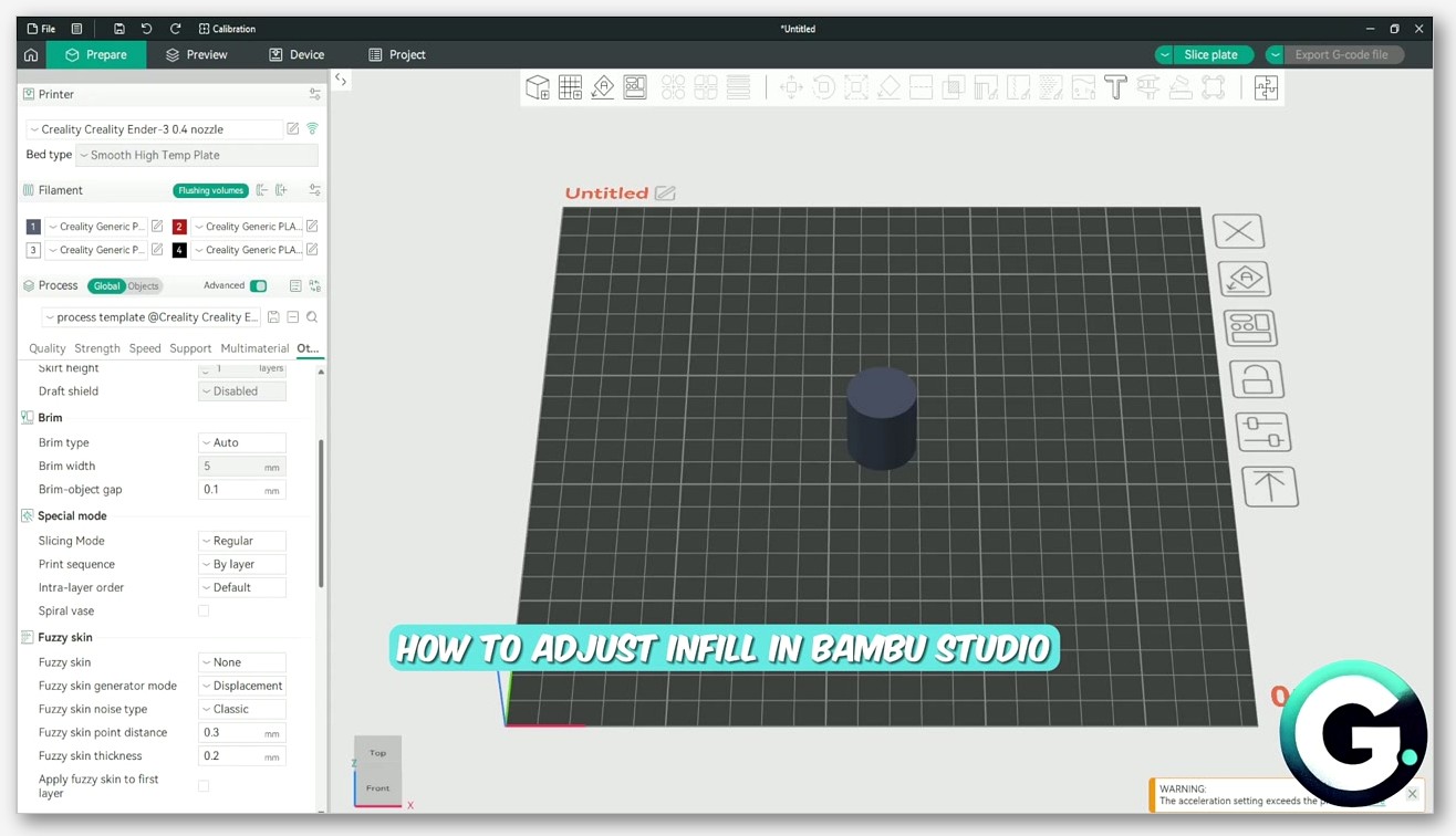
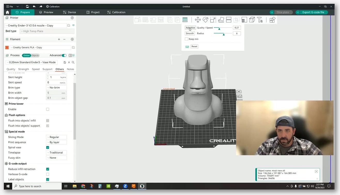
I open the Process settings panel on the right of the OrcaSlicer window. I switch to the Others tab. I scroll down to the Special mode section. I find a checkbox labelled “Spiral vase” there. That’s it. Tick it and the slicer immediately applies a cascade of changes that I’ll cover in the next section.
I want to flag the internal config key explicitly: it’s spiral_mode. If you go reading older PrusaSlicer or Slic3r references, you’ll see the key called spiralize, and PrusaSlicer’s print-setting variant is called spiral_vase. Neither of those will work as the OrcaSlicer key. If you’re editing a profile JSON by hand, or scripting OrcaSlicer through its CLI, the property you want is spiral_mode. I’ve checked the OrcaSlicer wiki page for the Special Mode section, which confirms that’s the variable name and that the description is verbatim “Spiral vase mode transforms a solid model into a single-walled print with solid bottom layers, eliminating seams by continuously spiralling the outer contour.”
If you don’t see the four sub-settings I’m about to cover, your parameter mode is probably set to Simple. I switch to Advanced in the dropdown at the top of the Process panel and the additional fields appear. The base Spiral vase checkbox itself is visible in Simple mode, but Max XY Smoothing and the two flow ratio settings are Advanced-only.
Quick history anchor: the spiral codepath was rewritten in OrcaSlicer 1.9 / 1.9.1, and that’s when the Smooth Spiral option was added. So if you’re on a very old 1.8 or earlier build, the Smooth Spiral checkbox won’t be there. I’d update before tuning anything. The rest of this guide assumes you’re on 2.3.x. If you’re new to the broader slicer and want the parent reference, I’d point you at the OrcaSlicer settings master guide first.
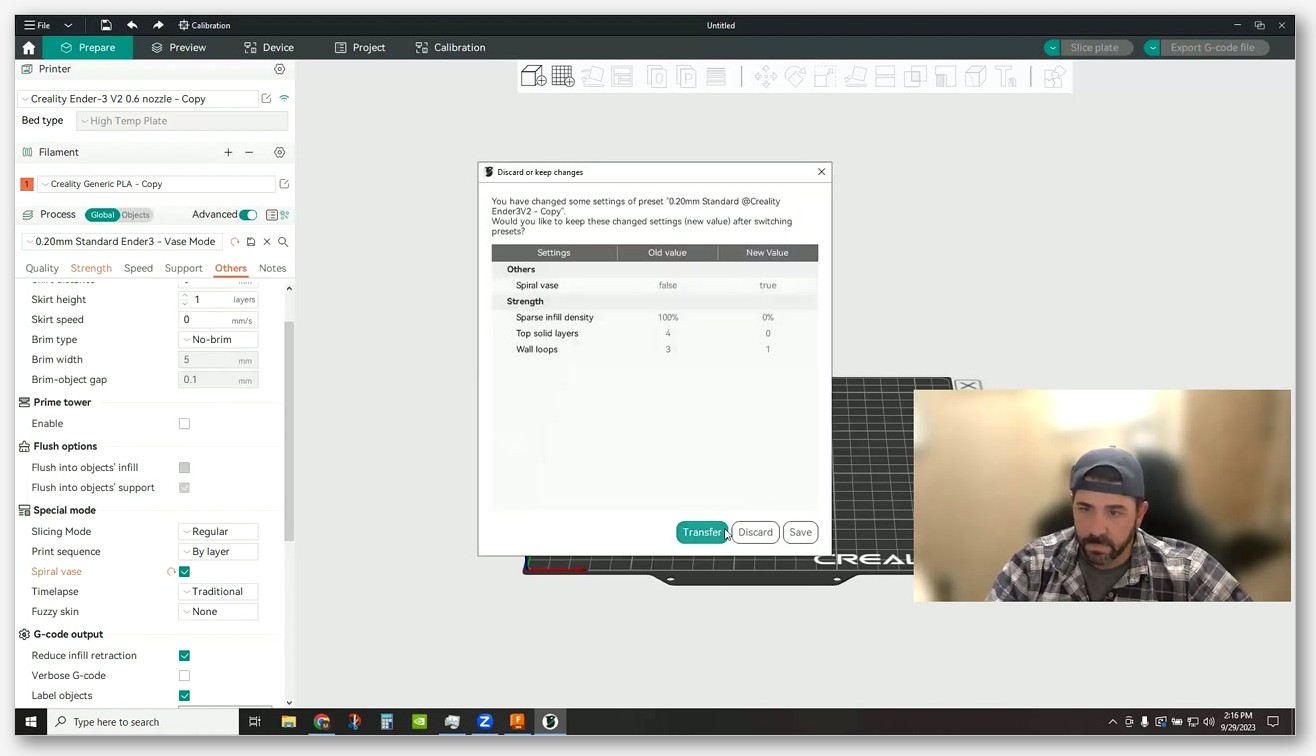
What the slicer forces the moment you tick the box
I think this is the part that throws people. Spiral vase mode isn’t just a single switch. The moment you check the box, OrcaSlicer overrides several other settings and locks them. I’ll point you at the Obico deep-dive, which puts it this way: “Spiral mode is accessible only when the wall loop is 1, support is disabled, top shell layer is 0, sparse infill density is 0, and the timelapse type is traditional.” In practice, OrcaSlicer enforces those for you when you enable spiral mode, so you don’t have to set them by hand.
The forced changes are:
- Wall loops = 1. Only the outer perimeter prints. You cannot have two or three perimeters in spiral mode by definition, because the head is climbing on a single continuous helix.
- Sparse infill density = 0%. There’s nothing to fill. The model is hollow by design.
- Top shell layers = 0. There’s no top. The spiral just ends when it reaches the top of the model.
- Supports = off. Supports require multiple separate toolpaths per layer, which fundamentally breaks the single-spiral assumption.
- Timelapse type = Traditional. Smooth timelapse mode interferes with the continuous spiral motion, so it’s forced to the simpler Traditional variant.
I want to flag one important thing the slicer does not strip: bottom layers. The base of your vase still prints normally with solid bottom layers, and only after the base is complete does the spiral begin. I’d point at the OrcaSlicer wiki, which phrases this as “single-walled print with solid bottom layers.” Prusa’s docs describe the same behaviour and note that you can adjust the number of bottom solid layers. So if your model has a flat bottom, you’ll get a proper sealed base, and then the spiral kicks in for the walls.
I think that bottom-layer behaviour is what makes spiral vase mode actually usable for things that hold water, like planters and flower vases, as long as the wall itself is sealed and the bottom layers are clean. I’ll come back to wall thickness and watertightness later, because there’s nuance there.
The four sub-settings explained
Once you’ve ticked Spiral vase and you’re in Advanced parameter mode, you get four extra settings exposed in the same Special mode section. I’m using the verbatim names from the OrcaSlicer wiki below:
Smooth Spiral (spiral_mode_smooth)
I treat this as the headline addition from the 1.9 rewrite. The wiki description, verbatim: “When enabled, Smooth Spiral smooths out X and Y moves as well, resulting in no visible seams even on non-vertical walls.” In plain English: even though the standard spiral has no Z seam, you can still get a tiny visual artefact at the spiral’s start or end, especially on a non-vertical wall. I think of Smooth Spiral as XY smoothing applied to that transition so the wall looks unbroken even where the spiral begins and ends.
I want to flag one caveat the wiki explicitly calls out: “If you are using absolute e distances, the smoothing may not work as expected.” Most modern firmwares use relative E by default, but if you’ve got an older config or you’re using one of those firmware forks that defaults to absolute extruder distances, the smoothing logic can produce odd results. I’d check your start G-code for an M83 (relative E) command if Smooth Spiral isn’t behaving.
I leave Smooth Spiral on by default. I only turn it off when I’m troubleshooting an unusual artefact and want to isolate whether the smoothing logic is contributing.
Max XY Smoothing (spiral_mode_max_xy_smoothing)
I think of this as the strength dial for Smooth Spiral. Wiki description, verbatim: “Maximum distance to move points in XY to achieve a smooth spiral. If expressed as a percentage, it is calculated relative to the nozzle diameter. Higher values allow more smoothing but may distort the model slightly.”
If you set it to 200%, the slicer is allowed to nudge points in XY by up to twice the nozzle diameter (0.8 mm on a 0.4 mm nozzle) to make the spiral transition look seamless. Push it higher and you get a smoother transition but you start losing fidelity to the original model. Push it lower and the smoothing has less room to work, and you may still see a faint mark. I leave it at the default and only adjust if I can clearly see a seam after a couple of test prints.
Spiral starting flow ratio (spiral_starting_flow_ratio)
Wiki description, verbatim: “Sets the starting flow ratio when transitioning from the last bottom layer to the spiral.” I’ll explain why this exists. When the printer finishes the solid bottom layers and starts the spiral, it’s transitioning from a layer where it’s depositing a lot of material into a much thinner single-wall context. Depending on your nozzle pressure and retraction settings, you can get a brief over- or under-extrusion right where the spiral begins. I’d describe the starting flow ratio as a scale knob for the extrusion at that transition.
If you’re seeing a thin, weak ring at the very bottom of the spiral walls, just above the solid base, I’d bump this up by 0.05 to 0.1. If you’re seeing a fat, blobby ring there, drop it. The default is sensible for most filaments. I’ve only really had to touch this on glittery PLA where the flow characteristics are a bit unpredictable, and on a very wet PETG that was puffing out at any extrusion change.
Spiral finishing flow ratio (spiral_finishing_flow_ratio)
Wiki description, verbatim: “Sets the finishing flow ratio when ending the spiral.” I think of it as the same idea as the starting ratio but at the top. As the spiral terminates, the head needs to gracefully reduce flow so you don’t get a blob at the rim of the vase. I leave the default in place most of the time. If your top edge is collapsing or thinning, ease this up. If you’re getting a fat lip at the top of every vase, ease it down.
I’d call these two flow ratios some of my favourite quality-of-life additions to OrcaSlicer’s vase mode. I used to fight transitions with PrusaSlicer years ago, and having a discrete knob for “the moment the spiral starts” and “the moment it ends” makes troubleshooting much faster. If your wider flow calibration is already dialled in, you’ll usually only need a tiny nudge here, not a major swing.
Model design rules the slicer expects
I’d say this is where most of my vase prints used to fail. Spiral vase mode has a specific set of expectations about the geometry you feed it, and OrcaSlicer will not warn you when your model violates them. I’ve watched it just produce a bad print without a single popup.
I lean on the Prusa Knowledge Base for the cleanest phrasing: “The model should be defined as a solid. Otherwise, PrusaSlicer will try (and fail) to create both inside and outside surfaces, so model the outside dimensions only.” I’d say that advice applies word-for-word to OrcaSlicer. If your STL has both an inner wall and an outer wall (typical of any model that was “hollowed out” in CAD or in a slicer’s hollowing tool before export), the spiral logic will see two perimeters per layer and try to print both. I’ve watched that produce a double-walled mess with bad bridging between the two walls, exactly the failure I described in the intro.
I’ve gathered the other rules from primary or reputable secondary sources:
- Single continuous outer surface from bottom to top. No branching, no separate sub-objects glued together. I’d point at the Obico writeup, which describes this as “a single continuous perimeter from bottom to top.”
- No internal walls or floating features. The Creality blog puts it as needing “no internal walls or floating features.”
- No flat horizontal tops. Same Creality reference, “no flat horizontal tops.” I think of the spiral as having nowhere to go if you cap it with a horizontal surface.
- No holes in the side wall. A hole means the perimeter would have to stop, jump, and restart, breaking the spiral.
- One object at a time only. Prusa’s docs: “Only one object at a time can be printed in the vase mode.” I’ve found OrcaSlicer to be the same. You cannot spiral two vases on one plate. I’d note that an old declined request, Issue #1399, for per-object vase mode toggles, has never been implemented.
- Watch your overhangs. Spiral vase has no supports and only a single wall, so significant horizontal overhangs will either droop or collapse. I’m not going to invent a specific maximum angle because there’s no primary source for the commonly quoted 30 to 45 degree figures, but in practice if it looks scary you should test a small version first.
I want to note that “model the outside dimensions only” is not the same as the buzzword “watertight mesh.” Prusa’s phrasing is “defined as a solid,” which means the model should be a single closed solid body. I’d argue a solid body is necessarily manifold, but the practical instruction is: don’t pre-hollow it, just model the outer shape and let vase mode do the hollowing at slice time.
Designing your own vase in CAD without breaking spiral mode
If you’re rolling your own vases in Fusion 360, Blender, FreeCAD, OnShape, or whatever else, the rules above translate into a few specific habits. I’ll keep this generic because every CAD app does these primitives differently, and I don’t want to invent menu paths that aren’t accurate for your version. I’ve worked across enough of these apps to know the underlying ideas all map cleanly.
Model the outside dimensions only. Whatever modelling operation you use, the output should be a single solid body that represents the exterior of the vase. I avoid any “shell” or “hollow” or “wall thickness” operation. I also avoid boolean-subtracting an inner cylinder from an outer cylinder, because that creates a two-walled body that the slicer will dutifully spiralise as two walls, and you get the failure mode I described at the start.
If you want an open top, leave the top open in the model. Don’t cap it with a horizontal face. If you’re sketching a profile and revolving it, leave the inner edge of the top open rather than closing it off. If you’re lofting between cross-sections, end the loft at the top cross-section without a cap.
Sweep, loft, and revolve are vase-mode friendly. I’ve found any operation that produces a smooth, continuous outer surface translates directly into a printable spiral. Twisted vases, fluted vases, gently lobed vases, all work well. I’d describe the constraint as: the cross-section at every Z must be a single closed curve.
Avoid sharp horizontal overhangs. The wall is one extrusion thick, so it has very little ability to bridge or self-support. I get away with a gradual taper or flare. A sudden ledge that sticks out horizontally is going to droop. If your design needs a ledge, I’d replace it with a smooth curve.
Don’t add holes in the side wall. Decorative cutouts and windows break the spiral. If your design needs windows, I’d say vase mode isn’t the right tool for the job and you should print it as a normal thin-walled object with multiple perimeters.
I’ll add one more practical tip from experience: when you export to STL or 3MF, double-check the file with a viewer that shows wall count. If you can see two surfaces at any Z slice, something in your modelling pipeline introduced a hollow. I’d re-export from the solid body, not from a derived shell feature.
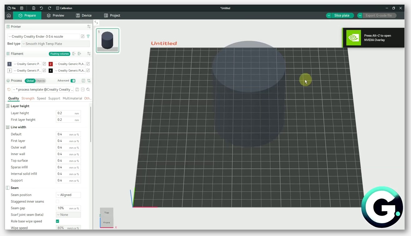
Layer height, extrusion width, and wall strength
I’d say the single biggest determinant of how strong your vase feels is the line width, not the layer height. A vase that’s printed at a 0.4 mm line width with a 0.4 mm nozzle is going to feel like crinkly tin foil. I’ve held vases printed at 0.8 mm line width with the same nozzle that feel like a proper pot. I can squeeze a much wider line out of a standard nozzle than most people assume.
I’ll point at the Creality blog, which recommends a layer height in the 0.2 mm to 0.25 mm range and a line width in the 0.6 mm to 0.8 mm range for vase-mode strength. I treat that as a sensible starting point on a 0.4 mm nozzle. All3DP’s guide frames it differently: extrusion width “between 100-120% of the nozzle diameter” for safe quality, going up to “about 2x the nozzle diameter” if you’re willing to accept some quality loss. I read that as: with a 0.4 mm nozzle, anywhere from 0.4 to 0.8 mm is technically achievable.
I’d be aware of these trade-offs:
- Wider lines mean a stronger, thicker, more opaque wall. I reach for them on planters and structural vases.
- Wider lines also mean less surface detail. If you’ve designed a vase with fine surface texture or a tight twist, a 0.8 mm line is going to smooth that out.
- I think a taller layer height combined with a wider line is the fastest way to get a strong vase printed quickly. It reduces total layer count and gives each layer more material.
- A shorter layer height combined with a narrower line gives you a more delicate, more translucent wall, but it takes much longer and is more fragile.
I usually run 0.24 mm layers with a 0.6 mm extrusion width on a 0.4 mm nozzle for general purpose vases, and bump to 0.8 mm width when I want a planter that can handle being moved around with wet soil in it. If you’ve got a 0.6 mm nozzle, I push line widths up into the 1.0 to 1.2 mm range, and the resulting walls feel almost ceramic in stiffness.
I’d argue flow calibration matters more here than for normal prints, because every imperfection in extrusion is visible on a single-wall surface. There’s no infill to hide behind. If you haven’t run a flow calibration on your filament recently, I’d do that before you start tuning vase mode. The starting and finishing flow ratios in the previous section won’t save you if your baseline flow is off.
Speed, temperature, cooling, and flow rate
I’ll note that OrcaSlicer’s wiki doesn’t prescribe specific vase-mode speeds or temperatures, so the numbers in community guides are recommendations rather than spec. I lean on All3DP’s suggestion: “A good guideline is 25 mm/s. If you have a very large object with a large circumference, you can increase the speed to 35-40 mm/s.” I’d also point at Discussion #3057 on the OrcaSlicer repo, which shows users running 20 to 30 mm/s on small-diameter vases and pushing to 80 mm/s on larger ones, with one user reporting they hit a flow rate ceiling on a very tall thin shell.
I’ll explain what’s happening physically. On a small-diameter vase, the head completes each spiral revolution very quickly, so the layer time is short and the previous layer hasn’t cooled enough to support the next pass. I either slow down or crank up cooling. On a larger-diameter vase, each spiral revolution takes longer, the previous layer has time to set, and I can go faster. I see the cap on speed being set by your printer’s volumetric flow rate, since you’re laying down a continuous fat line.
I generally start around 30 mm/s on a 100 mm diameter vase and adjust from there. On a 200 mm diameter planter I’ll push to 60 or even 80 mm/s. If you’re flow-rate limited, I’d watch for the print starting to under-extrude on the taller sections where the line width is at its max, and that’s the signal to slow down.
I’ll talk temperature next. The Creality blog says to “set higher than normal,” but doesn’t give a specific number, and I’m not going to invent one. The reasoning is sound, though. I think a slightly hotter nozzle improves layer adhesion between spiral passes, which matters because you only get one wall holding the whole vase together. I usually run 5 degrees C higher than my baseline for the same filament. If you’re on PLA, I’d check your filament’s recommended range and pick the upper end; if you’re on PETG, same logic.
I’ll talk cooling next. This depends heavily on the filament. PLA generally wants strong cooling at the higher end of the fan range to keep small-diameter vases from sagging. PETG wants less cooling, often around 30 to 50 percent on the part fan, because too much cooling kills layer adhesion and you’ll get a vase that splits along a layer line when you flex it. I’d push back on the universal “always 100 percent fan” rule for vase mode. I use my filament profile’s cooling defaults as the starting point. If you want the deeper dive, our PLA settings guide and the PETG settings guide cover the temperature and cooling defaults that I’d apply before tweaking for vase mode.
For watertight planters specifically, I reach for PETG. It’s more flexible, less prone to layer separation under hydrostatic pressure from wet soil, and bonds well to itself if you keep cooling moderate. I’ve used PLA too when I seal it with a couple of coats of polyurethane or a food-safe epoxy. Raw single-wall PLA will weep eventually.
What breaks the spiral: features that don’t work in vase mode
I wish I’d had this section bookmarked the first six months I used OrcaSlicer. I’ve watched several features either silently fail or fall back to inferior behaviour when combined with spiral vase. The slicer will not always warn you. I’ll walk through the current state of affairs in 2.3.x.
Modifier meshes and height range modifiers
I’ve tested this: height range modifiers, which let you change settings for a specific Z range of a print, do not work in combination with spiral vase. I’d point at Discussion #3621 on the OrcaSlicer repo, which is an open feature request, originally raised by user JonBerlin, who notes that “spiral vase mode in combination with the height range modifier” has never been implemented across Slic3r forks. As of 2026 the request is still open and unimplemented. So if you wanted to, say, change line width or temperature halfway up a vase, you can’t do it through height range modifiers in vase mode.
I’d put modifier meshes in general into the same bucket. The spiral logic operates on the overall outer perimeter, and per-region modifications don’t compose with it.
Multi-color and mid-print filament change
I want to be clear: you can’t change colour or filament mid-print in spiral vase mode in OrcaSlicer 2.3.x. Issue #891 has been open since April 2023, raised because PrusaSlicer allows adding filament-change G-code commands directly in the vase-mode preview, but the equivalent functionality is “disabled” in OrcaSlicer and Bambu Studio. The issue is still open.
I’d flag PR #8404, merged on 30 March 2025 with the title “Fix vase mode with filament change,” but read the change carefully. It specifically addresses the case where you want the raft printed in a different filament from the spiral body, by forcing the colour-change layer to print in normal (non-spiral) mode. I don’t see it adding general manual colour-change support in vase mode. So if you were hoping to do a gradient vase with a colour swap halfway up, that’s still not supported.
I’d also flag two earlier feature requests, “double-walled vase mode” (Issue #4789) and “spiralizable multi-wall” (Issue #4642), both closed as “not planned.” I read the official position as: vase mode is single-wall, single-filament, and that’s not changing soon. If you want multi-colour, I’d say you need a different workflow entirely, not vase mode.
Fuzzy skin (partial)
I’d say fuzzy skin technically works in vase mode but with a caveat in current 2.3.1 builds. I’ll point at Issue #11119, which is open and documents that if you select fuzzy skin with the “Extrusion” generator mode, the slicer silently falls back to “Displacement” mode when spiral vase is also enabled. I get a different surface texture than I’d expect from extrusion-based fuzzy skin. The print still completes, it just doesn’t look the way the setting suggests. If you’re hitting that, I’d send you to our fuzzy skin writeup for the full breakdown of the two generator modes.
Supports, top shells, and infill
I’ve covered earlier how all three are force-disabled when spiral vase is enabled. The slicer doesn’t ask, doesn’t warn, just turns them off. So if you have any of these on in your profile and you toggle spiral vase, I’d expect them gone. If you toggle vase off again later, they’ll come back at whatever values you set them to before.
Arachne wall generator
I get the question a lot: is the Arachne wall generator “disabled” in vase mode? The OrcaSlicer wiki page on the wall generator doesn’t explicitly say so either way, and no primary source I’ve found states that Arachne is forcibly switched off. What’s true is that spiral vase forces wall loops to 1, so the entire Arachne-vs-Classic distinction (which matters mostly when wall count is greater than one or when wall widths vary) is largely moot. I’d argue with only a single wall to generate, the choice between the two generators has little practical effect. I leave it on whatever my profile defaults to and don’t worry about it.
Printer-side caveats
I want to cover a few things that are about the physical printer rather than the slicer, and that disproportionately affect spiral vase outcomes.
First layer adhesion matters more than usual. I see the base of your vase as the only solid layer of structure the print has. If a corner lifts, you’ll see it propagate all the way up the spiral as a tilted or warped vase. I level my bed and run a first-layer test pattern before any vase longer than 100 mm tall. I find glue stick or a good textured PEI sheet helps. If you’re on a smooth PEI plate that’s seen heavy use, I’d give it a quick wipe with isopropyl alcohol before each vase, worth the 30 seconds.
Bed level is critical for circular vases. I’ve watched a round vase telegraph any bed unevenness as a wobble in the spiral. If you’re seeing one side of the vase look thinner than the other, your bed isn’t level. I’d run tramming or auto-bed-levelling to solve it. I see this much more obviously in vase mode than in normal prints because there’s nothing else on the layer to distract the eye.
Retraction during the spiral is irrelevant. The head never stops extruding during the spiral, so retraction settings don’t get exercised during the wall print. They do still matter for the bottom layers (travel moves on the base), so I don’t set retraction to zero. I just don’t waste time tuning it for the spiral itself.
Z wobble is brutally visible. A normal print can hide minor Z-axis inconsistencies under infill and multiple perimeters. A spiral vase has neither. I’ve seen any Z-axis play, a slightly bent leadscrew, a misaligned anti-backlash nut, show up as a horizontal ridge pattern on the wall. If you see suspicious banding on a vase that doesn’t show up on other prints, I’d say the vase isn’t lying to you, your Z axis has an issue.
Cooling fan duct matters. Because cooling is so important on tight-diameter vases, and because a vase puts the whole height of the print in line of sight of the part fan, I find a well-shrouded duct that aims at the print does much better than a generic side-blow setup. If you’ve upgraded to a better cooling solution at any point, I’d say vase mode is where you’ll most notice the improvement.
Troubleshooting common spiral vase failures
Here’s the failure-to-fix lookup table I’ve built over years of breaking vases. If you want a broader reference for non-vase issues, our general troubleshooting guide covers the wider failure modes.
Two visible walls instead of one
I’d say your STL is pre-hollowed. The slicer is doing what you asked. I’d re-export from a solid body in your CAD app, or find a different version of the model. There’s no slicer setting that fixes this; the geometry has to be correct.
Thin or weak ring at the very bottom of the spiral, just above the solid base
I’d increase spiral_starting_flow_ratio by a small amount, say 0.05 to 0.1. This adds material to the transition from the last solid layer to the spiral. If the issue persists, your overall flow calibration may be slightly low. I’d revisit calibration before pushing the start ratio higher.
Fat lip or blob at the top of the vase
I’d decrease spiral_finishing_flow_ratio by a small amount. The spiral is depositing too much material as it tapers off at the top.
Collapse or thinning at the top edge of the vase
I’d increase spiral_finishing_flow_ratio slightly. It’s the opposite problem. If the model itself has a sharp top edge, I’d round it slightly in CAD; sharp horizontal terminations are hardest to print cleanly in spiral mode.
Visible seam on the wall
I’d enable Smooth Spiral if it’s not on already. If it’s already on, check that you’re using relative E distances (look for M83 in your start G-code); Smooth Spiral has documented issues with absolute E distances. As a last resort, I’d increase Max XY Smoothing, accepting a small loss of model fidelity in return.
The bottom layers detach during the print
I’d call this a bed adhesion problem, not a vase mode problem. I’d improve your first-layer settings, clean your build plate, check first-layer Z offset. A spiral vase has no margin for losing the base; if it lets go even partially, the print fails.
One side of the vase looks thinner than the other
Your bed isn’t level. I’d re-tram or run an auto-level. It could also be Z-axis wobble, but I’d level the bed first.
Layer ridges or banding visible on the wall
I’d suspect a Z-axis mechanical issue. Inspect leadscrews, anti-backlash nuts, and Z couplers. It could also be temperature swing if your hotend is undersized for the layer time. I’d try reducing speed slightly first to see if the banding follows the speed change.
Missing partial layer
I’d call this a model topology problem where the slicer can’t make a clean perimeter at one Z slice. Issue #4093 covered this case and it was closed as not planned, with the resolution being “fix your model.” I’d re-mesh the STL, re-export from CAD, or check for non-manifold edges in a mesh repair tool.
Extra bottom layer on a 0.6 mm nozzle
I’d flag this as a real bug in OrcaSlicer 1.4.5 through 1.8.0, tracked as Issue #2344 and fixed in later 1.x via PR #2370. If you’re on any 2.x build, this is not your problem. If you somehow are on an old 1.x build, I’d update.
Known open issues to watch in 2.3.x
I’d flag three open issues to be aware of as I write this, because they affect specific vase mode use cases and you might hit them.
Issue #11490, bottom shell thickness disabled on 2.3.2-dev. I’ve seen this on a 2.3.2-dev build: enabling Spiral vase greys out the “bottom shell thickness” input even though “bottom shell layers” remains editable. It’s an open issue, reported in November 2025. I’d work around it by setting your bottom thickness through the layer-count field instead. If you’re on a stable 2.3.x release, you may not encounter this; it’s specifically called out on the dev build.
Issue #11119, fuzzy skin extrusion mode falls back to displacement on 2.3.1. I’ve covered this earlier. Open since October 2025. If you need fuzzy skin extrusion behaviour specifically and you’re on 2.3.1, I’d warn that it silently reverts to displacement mode when combined with spiral vase.
Issue #891, no mid-print filament change in vase mode. Open since April 2023. As I covered above, you cannot add a manual filament change partway up a spiral vase in OrcaSlicer 2.3.x. I’d remind you that PR #8404 only fixed the raft case.
I wouldn’t call any of these showstoppers for the common vase-mode workflow. You can print great vases without ever touching fuzzy skin, the bottom shell thickness input, or mid-print filament changes. But if you’re planning a project that depends on one of these, I’d check the linked issues for the current status before committing time to it.
FAQ
Can I print two vases at once in spiral vase mode?
No. I’ve tested it: spiral vase mode supports one object per print, full stop. I’d call this a Prusa-era limitation that OrcaSlicer inherited, and there’s a long history of declined feature requests for per-object vase mode (Issue #1399 among them). If you want to print multiple vases, I’d run them as separate prints back-to-back.
Can I change colour or filament partway up the vase?
Not in OrcaSlicer 2.3.x, no. Issue #891 has been open since 2023, and the merged PR #8404 only fixed the specific case of having the raft print in a different colour. I’d note there’s no GUI for inserting a manual filament change in the spiral itself.
Do supports work in vase mode?
No, supports are force-disabled the moment you tick the Spiral vase checkbox. If your model has overhangs that need supports, I’d say vase mode isn’t the right tool. I’d use a normal print with thin walls instead.
Does Arachne vs Classic wall generator matter in vase mode?
Not really. Spiral vase forces wall loops to 1, so the entire distinction between the two generators (which matters when there are multiple walls or when wall width varies) is mostly moot. I’d leave it at your profile default and not worry about it. No primary source says Arachne is explicitly disabled; the difference just doesn’t show up with only one wall.
Is the bottom of my vase solid?
Yes. I’ve confirmed spiral vase mode still prints the bottom solid layers in normal (non-spiral) mode, and the spiral only begins after the base is complete. So you’ll have a proper sealed bottom on your vase as long as you’ve got bottom solid layers set to a sensible value (usually 3 to 5).
Can I use vase mode with PETG?
Yes, and for watertight planters or anything that’s going to hold liquid, I’d reach for PETG over PLA. It’s more flexible and less prone to layer separation under pressure. I’d just keep cooling moderate (around 30 to 50 percent part fan) rather than maxed out, because too much cooling on PETG kills layer adhesion and you’ll get a vase that splits along a layer line.
Can I add a height range modifier to change settings mid-vase?
No. I’d note height range modifiers in combination with spiral vase have never been implemented in any Slic3r-family slicer. Discussion #3621 has been open since 2024 as a feature request and is still pending. If you need different settings at different Z heights, I’d say you can’t get there from here.
Why does my vase look like it has two walls?
Your STL was pre-hollowed in CAD before export. I’d say the slicer is correctly spiralising both walls because both walls exist in the geometry. I’d re-export from a solid body in CAD with the outside dimensions only, and let vase mode do the hollowing at slice time.
I think spiral vase mode is one of those features that’s genuinely magical when the model and the settings line up, and genuinely frustrating when they don’t. I’d describe the big mental shift as realising the slicer isn’t doing anything clever to your model; it’s taking the outer perimeter of a solid body and tracing it as a continuous helix. Everything else, the model rules, the forced setting overrides, the troubleshooting steps, falls out of that one mechanism. I’d say: get a clean solid body, tick the box, leave the bottom solid layers in place, dial in line width for strength, and you’ll get vases that look better than the ones I broke for years figuring this out. If you want to download or update OrcaSlicer to the version this guide was tested against, I’d grab the latest release from the official OrcaSlicer GitHub releases page, and use the rest of orcaslicer.net for the wider Process settings context when prints misbehave.
Related OrcaSlicer guides
- OrcaSlicer for Beginners: Your First Print in 15 Minutes
- OrcaSlicer Modifier Meshes: Different Settings on One Model
- OrcaSlicer Custom G-code: Start, End and Layer-Change Macros
- How to Install OrcaSlicer on Linux: AppImage, Flatpak, AUR
- OrcaSlicer for Elegoo Neptune 4 / Pro / Plus / Max: 2026 Setup Guide