
My first multi-color print in OrcaSlicer was a tiny pixel-art keycap, and I spent maybe ninety minutes painting individual triangles before I realised the Fill tool exists. I’d been clicking facet by facet like a person carving runes into bark. When the keycap finally came off the plate with three clean colours, I felt smug for about ten seconds before noticing the purge waste tower next to it was bigger than the keycap itself.
That’s color painting in OrcaSlicer in one paragraph. It’s powerful, it’s not difficult once you understand what the five brush tools actually do, and it’ll teach you very fast that purge volume is the real cost of multi-colour 3D printing. I’ve now painted enough Venn diagrams, Pokeballs, name plates, and Hextraction tiles to have a clear sense of which workflows survive contact with reality and which ones look great on YouTube but collapse the moment your printer doesn’t have an AMS bolted to its side.
This guide covers what color painting actually is inside OrcaSlicer 2.3.x, the five brush tools you’ll use to mark up models, how painted regions map to filament slots on hardware that ranges from a Bambu X1C with four chained AMS units down to a stock Creality Ender 3 with a Klipper macro. I’ll also cover the stuff the official wiki glosses over: paint depth (it doesn’t exist yet), MMU3 (use PrusaSlicer instead), and how to keep purge volumes from eating an entire spool on a four-colour Benchy.
- What color painting actually is (and what it isn’t)
- Finding the Color Paint mode in OrcaSlicer 2.3.x
- The five brush tools, one by one
- Height range, color filter, and the missing “paint depth”
- Importing colors from images: HueForge, Fuzzyficator, and the myth of native projection
- Painting workflow on a Bambu printer with AMS
- Painting workflow on a single-extruder printer with M600 or PAUSE
- IDEX dual-extruder workflow, plus the MMU3 sidebar
- Flushing volumes and the purge matrix
- Where the prime tower fits in
- Common mistakes (and how I’ve fixed them)
- Per-printer notes: X1C, A1, J1, SV04, Voron, Ender, Anycubic
- FAQ
What color painting actually is (and what it isn’t)
Color Painting is the in-slicer mode that lets you mark different regions of a single mesh with different filament slots, so the slicer generates filament-change events at the right points during the print. The official OrcaSlicer wiki puts it like this: “Color Painting allows you to paint specific areas of your 3D model with different colors in the Prepare tab. This feature is useful for visualizing different sections of your model, planning multi-material prints, or simply adding a creative touch to your design.” That’s accurate, but it understates how distinct the workflow is from two other things people confuse it with.
The first is multi-object color assignment. If your scene has three separate STL files on the build plate, you can right-click each object and assign it to a different filament slot. That’s not painting; that’s by-object coloring. It’s the right answer when each colour belongs to a completely separate part. The painted-region workflow is for when you’ve got one mesh and you want different surfaces of that mesh to be different colours, like the differently-coloured rings of a 3-color Venn diagram printed as one model.
The second confusion is what people call “MMU split” or “AMS color split.” That’s the automatic slot management that happens when a 3MF you downloaded from MakerWorld or Printables already encodes per-region colours. OrcaSlicer reads the file, shows you the painted regions, and lets you remap which physical filament slot maps to each painted color. You aren’t painting anything; you’re consuming someone else’s paint job. The reassignment happens from the Filament panel before slicing.
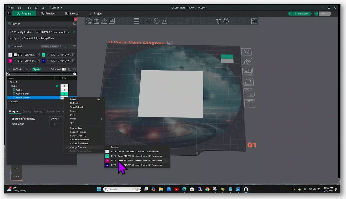
Color Painting is the only one of those three that takes a single contiguous mesh and puts multiple colors on different surfaces without splitting the STL. If you find yourself trying to import three separate STLs and paint them in the scene, stop. You want the by-object filament assignment instead, and the right-click “Change Filament” submenu is your friend there.
One more concept that has to land before the brushes make sense: color painting is binary per facet. Each triangle of the mesh belongs to exactly one filament slot at slicing time. There’s no blending, no gradient, no anti-aliased edge. If you want a soft transition between two colours, you have to fake it by alternating thin horizontal bands of each color within a height range, and the print result still looks like banding because that’s literally what it is.
Finding the Color Paint mode in OrcaSlicer 2.3.x
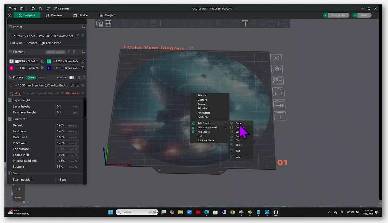
Open OrcaSlicer, load an STL or 3MF, and stay on the Prepare tab. On the left-hand vertical toolbar you’ll see icons for Move, Rotate, Scale, Place on Face, and a cluster of painting icons further down: Support Painting, Seam Painting, and Color Painting. The Color Painting icon is the one that opens a side panel with the five brushes and the active-filament slot selector.
You can also right-click any object in the scene and choose Color Paint from the context menu. Same destination, different route. Clicking the toolbar icon a second time exits the painting mode and bakes your strokes into the mesh’s painted-region metadata. The painted regions are saved into the 3MF when you save the project, so if you do all your painting work, save, then come back the next day, your strokes are still there.
Version compatibility is worth a quick note. The five brush set, the Edge Detection toggle on Fill, and the Gap Fill option are all present in OrcaSlicer 2.3.x. Earlier 2.0 builds had the same UI shape but suffered from issue #5152, where painted vertical walls didn’t trigger filament changes on the vertical shells when filament shrinkage wasn’t set to 100%. That bug was closed by PR #6507, so if you’re on a 2.3.x build (and you should be), painted vertical surfaces produce filament changes on vertical walls exactly as you’d expect. The 2.3.2 release also added a wipe-tower-type selector (including a sturdier Type 2 variant for MMU and tool-changer setups), which matters less to color painting itself but does affect how the purge column on your bed looks at print time.
You can grab the current release from the OrcaSlicer GitHub releases page; the official orcaslicer.com download links route there anyway. I’d avoid pre-release alpha builds for any actual print job you care about, because painting bugs in alpha builds aren’t always backwards-compatible with project files saved in stable builds.
The five brush tools, one by one
OrcaSlicer’s color painting interface exposes exactly five brushes. PrusaSlicer users will recognise the family but the names are different, and you’ll see writers online refer to a “Smart Fill” tool that doesn’t exist in OrcaSlicer’s UI by that name. What OrcaSlicer actually labels them is what I’ll use here.
Circle
The wiki calls Circle “a circle-shape pen tool used to draw any curves on the model’s surface.” Practically, it’s the brush you’ll use most. Hold left-click and drag, and Circle paints every visible facet under the cursor with the active filament colour. The brush radius is set with the slider on the side panel, not by mouse wheel by default, which is the first thing I trip over every time I come back to OrcaSlicer after a break. Circle is “visible facets only,” meaning it doesn’t paint hidden interior facets even if they’d geometrically fall inside the brush radius from your viewing angle. That’s a good default for most cosmetic painting work.
Sphere
Sphere is Circle’s evil twin. Same shape, same drag behaviour, but it paints every facet inside the sphere volume around the cursor, including hidden interior facets and the back side of thin walls. This is occasionally what you want (painting the inside of an open vase, say), but more often it’s what causes mysterious filament changes that don’t show up on the print and burn through purge volume for invisible reasons. If a painted area is causing more swaps than you can see on the model, switch to Circle and repaint that region.
Triangle
Triangle is precise and slow. Click once and the single triangle facet under the cursor takes the active colour. Drag and a string of facets get painted in sequence. The limit of this tool is your mesh resolution. If you’ve got a smooth STL exported at 50,000 triangles, you can do beautiful pixel-level work with Triangle. If you’ve got a chunky low-poly model with 200 triangles total, Triangle paints in obvious wedges and you’ll want Fill instead. I use Triangle mainly for fine cleanup along the boundary between two painted regions, where Circle or Fill left a few stray facets in the wrong colour.
Height Range
Height Range is the brush I wish I’d discovered earlier. The wiki describes it as colouring “all facets between a given height range, even though they may lay in disjointed regions.” You pick a minimum Z and a maximum Z in millimetres, click apply, and every facet between those heights gets the active colour, regardless of which side of the model it’s on. This is the canonical tool for banded multi-colour: bottom 10 mm of a vase in blue, middle 15 mm in white, top 5 mm in red, three clicks and you’re done.
Important detail people miss: Z on the mesh is continuous, not layered. You set the range in millimetres, not layer numbers. If your layer height is 0.2 mm and you set a Height Range from 5.0 to 5.1 mm, you’ve asked the slicer to colour a band shorter than one layer, and the painted region will not survive slicing. Paint regions at least 0.5 mm tall in Z to be safe, and at least 1 mm if you want the colour to be visibly distinct on the surface.
Fill
Fill is the bucket-fill of the bunch. The wiki: “Colorizes a bucket of connected facets propagated from the facet pointed by the mouse pointer. The propagation stops when reaching a facet that has a different color.” That’s the standard behaviour with Edge Detection on. With Edge Detection off, Fill ignores angle changes and floods across the entire connected mesh until it hits a region already painted in a different colour. The angle threshold for Edge Detection is configurable on the side panel.
The pro tip that every OrcaSlicer power user eventually finds, surfaced in the mcgybeer tutorial as well as scattered through the GitHub discussions: to re-color an already-painted region, switch to Fill, uncheck Edge Detection, and click on the painted facet. Fill will replace the entire painted patch with the new colour in one click. This is the answer to the recurring “how do I change one painted region without manually repainting it” question that’s been raised in discussions like #5363, and it works perfectly today even though the request for a dedicated “color replace” tool is still open.
The Gap Fill option
Gap Fill isn’t a brush, it’s a toggle on the panel. When enabled, OrcaSlicer automatically fills small gaps in your painting strokes within the Gap area size defined. If you’ve ever painted a region with Circle and ended up with a sprinkling of unpainted facets inside the painted area (because the brush hit those facets at an awkward angle), Gap Fill cleans them up. I leave it on for free-hand work and turn it off when I’m being precise with Triangle.
Hotkeys and brush size
The only hotkeys you can rely on inside color painting mode are the number keys 1 through 9. Pressing 1 selects filament slot 1 as the active painting colour, 2 selects slot 2, and so on up to the number of filaments actually loaded in your project. Pressing a number higher than the number of filaments active does nothing. Brush size on Circle and Sphere is the side-panel slider; there isn’t a verified mouse-wheel binding by default. I’ve seen tutorials invent hotkeys like “D for paint depth” or “B for brush size,” and they don’t exist. Stick to the verified 1-9 slot selection and use the side panel for everything else.
Height range, color filter, and the missing “paint depth”
This is the section where I have to be careful, because two things look similar and aren’t. Height Range, the brush I covered above, does exactly what it says: it colours facets between two Z values on the surface of the mesh. That’s a surface operation. The painted region is on the outside (and any disjointed surfaces inside the height band), and the slicer turns that into filament-change events at the right layer heights.
What Height Range does not do is push the painted colour into the walls or infill of the model. If you paint the top of a cube red and the bottom green, the outer surface of the boundary will switch colours at the right layer, but the wall behind the surface (and the infill within) is determined by the slicer’s normal wall-counting and infill-routing logic. With one perimeter, the colour change is one wall thick. With three perimeters, the new colour has to overcome the old colour through three walls of bleed before it shows clean.
Users have been asking for a “paint depth” slider for years. Issue #12166 captures the request: “the color painting tool does not paint all the way through the walls and infill of the model, causing undesired color bleeding.” The issue is open. As of the 2.3.x line, OrcaSlicer does not currently support a user-adjustable paint depth. Don’t believe content that claims otherwise. PrusaSlicer’s MMU painting does extend painted regions inwards automatically via a parameter called mmu_segmented_region_max_width, which is one of the reasons PrusaSlicer users have an easier time with painted external regions that don’t bleed. The honest comparison to make is: OrcaSlicer paints the visible facets you select, and color carry-through into walls is determined by wall count and infill behavior, not a paint-depth slider.
The practical workaround, until that feature lands, is to increase your wall count for any model where bleed-through would be visible (most thin-walled prints), or use a multi-layer painted boundary in Z so the colour change occupies several layers and bleed isn’t visible on the seam. For tall slim text on the side of a model, four perimeters and a 0.5 mm tall painted band tend to look clean even when looked at from a glancing angle.
One historical note worth flagging because it confuses people reading old forum threads: issue #5152 documented a bug in OrcaSlicer 2.0.0 where filament changes were only applied to top and bottom shell layers, not to vertical shells, when filament shrinkage handling was off the default. That bug was fixed by PR #6507 and closed before the 2.3 line stabilised. If you’re on 2.3.x, painted vertical surfaces produce filament changes on vertical walls as expected. Don’t mistake the closed bug for current behaviour.
Importing colors from images: HueForge, Fuzzyficator, and the myth of native projection
I see this claim circulated constantly: “OrcaSlicer lets you project a 2D image onto your model and auto-assigns colours.” It does not. There is no built-in feature in OrcaSlicer 2.3.x that takes a PNG or JPG and paints it onto a mesh by mapping pixel colours to filament slots. Any tutorial that tells you to “click Import Image inside Color Paint mode” is hallucinating or describing a different slicer.
What does exist is a workflow that gets you the same outcome by combining two or three tools.
The dominant tool for converting a 2D image into a multi-colour print is HueForge. HueForge analyses an image, predicts how the colours of your physical filaments stack to produce intermediate hues through transmission, and outputs a STL or 3MF where layered filament regions produce the image. You then open that file in OrcaSlicer, verify the painted regions look right, slice, and print. HueForge is the standard answer to “I want to print this photo of my dog.” The output is closer to a lithophane in technique than a paint-by-numbers operation.
A different approach is Fuzzyficator, an open-source extension that uses a displacement-style image to paint surface textures by raising and depressing the mesh, rather than by assigning colours. Hackaday covered it in early 2025 (the headline was something like “Software Lets You Paint Surface Patterns on 3D Prints”) and 3printr did a writeup around the same time. It works with PrusaSlicer, Bambu Studio, and OrcaSlicer. The output is texture, not colour, but it solves a related problem: getting the visual interest of an image into a print without printing four-colour multi-material.
The third pathway, and honestly the one most users end up on, is to grab a pre-painted 3MF from MakerWorld, Printables, or a friend’s project share. The painted regions are already encoded in the 3MF, OrcaSlicer reads them, you remap the slots to your actual filament colours from the Filament panel before slicing, and print.
So if someone tells you “OrcaSlicer can paint your model from an image,” what they actually mean is: HueForge generates a paintable mesh from your image, and then OrcaSlicer prints it. The slicer’s job is the slicing; the image-to-mesh translation happens outside.
Painting workflow on a Bambu printer with AMS
The Bambu AMS workflow is the smoothest case, and it’s the one most YouTube tutorials demo because the UI hides almost all the complexity. Here’s the actual end-to-end on an X1C or P1S with one AMS unit, four spools loaded.
Load the STL or 3MF into OrcaSlicer. In the Filament panel on the left, you’ll see your AMS slots listed. If OrcaSlicer is paired with your printer, the AMS spool colours autopopulate. If not, click each slot and pick a filament profile that matches the physical spool. Add as many slots as you need painted colours, up to four with a single AMS or higher with chained AMS units (the X1C supports up to four chained AMS for 16 total slots, though purge cost scales accordingly).
Open Color Paint mode. Press 1 to make slot 1 active, paint with whichever brush you like, press 2 for slot 2, repeat. Exit Color Paint mode by clicking the toolbar icon a second time. Switch to the Preview tab and slice.
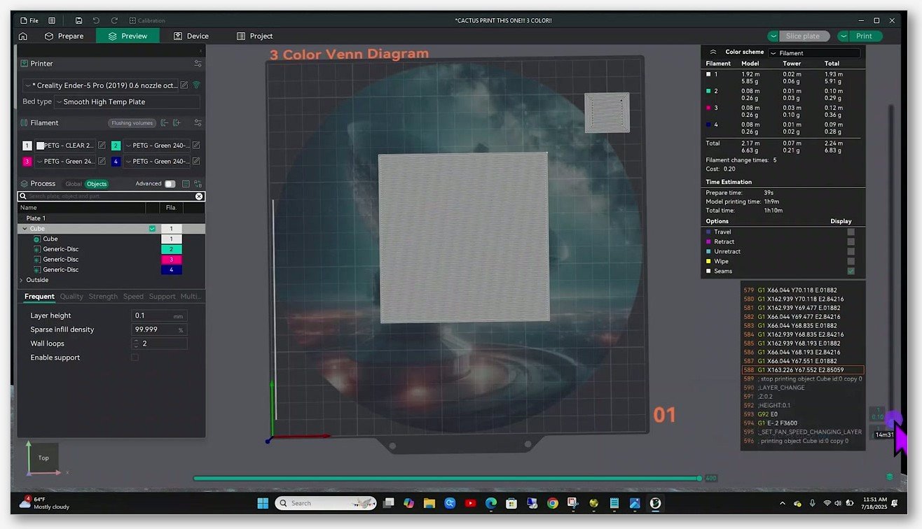
In the slice preview, OrcaSlicer’s color scheme panel on the right shows you a breakdown by filament: model material, tower material, total material, in metres and grams. This is your reality check before sending the print. If you painted a region you intended to be 5 percent of the model and the preview says it’s 40 percent of the total filament because of purge, something’s off; usually too many color transitions per layer, or a flushing multiplier that’s too high.
Send the sliced job to the printer via the cloud (post-January-2025 firmware routes through Bambu Connect for cloud sends, or you can use LAN-only mode for local-only operation). The AMS handles the cuts and swaps. The slicer’s job is the toolpath and the wipe tower geometry; the printer’s job is the filament loading and unloading. You don’t intervene during the print.
A1 and A1 mini with AMS Lite follow the same workflow, just with the external 4-slot AMS Lite instead of the chambered AMS. The H2D introduces a dual-nozzle wrinkle (covered in the IDEX section below), but for a single-nozzle AMS printer the painting workflow is identical across the X1 and P1 families.
If you’re brand new to AMS setup, the sibling article on configuring the Bambu AMS in OrcaSlicer walks through the filament profile pairing in more detail. For the X1 and P1 hardware specifics, the X1C and P1S printer profile setup article covers the printer-side config. And the multi-material printing pillar covers the broader question of which approach (color painting, by-object assignment, or downloaded 3MF) suits which type of model.
Painting workflow on a single-extruder printer with M600 or PAUSE
Plenty of people want multi-colour prints without spending several hundred dollars on an AMS. The answer is the manual filament change workflow, triggered in g-code by M600 (Marlin) or PAUSE (Klipper). It is genuinely usable for two-colour and three-colour models if you accept that you’ll be standing next to the printer at filament-change time.
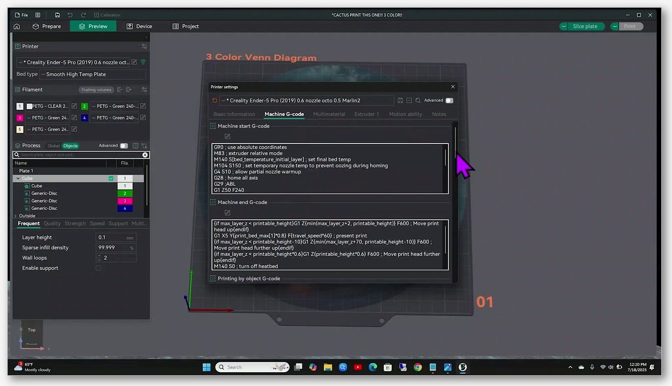
The setup is in Printer Settings → Machine G-code → Change filament G-code. The default in most non-Bambu printer profiles is either M600 or PAUSE, depending on the firmware family. If your printer profile has a blank Change Filament G-code, the printer will not pause at all and your multi-colour print will come out solid in whichever filament was loaded. This is the single most common gotcha for new users.
Marlin firmware requires M600 to be enabled at compile time. The ADVANCED_PAUSE_FEATURE and NOZZLE_PARK_FEATURE compile flags in Configuration_adv.h have to be on. Stock Creality Marlin builds on older Ender 3 boards do not ship with M600 enabled by default. If your stock-firmware Ender 3 has been ignoring your M600 commands, that’s why. The fix is either to flash a Marlin build that has M600 compiled in (the Marlin docs at marlinfw.org/docs/gcode/M600 cover the compile flags), move to Klipper, or use a Sonic Pad / Octoprint setup that injects a pause via the host rather than the firmware.
Klipper printers (Voron 2.4, RatRig V-Core, Sovol SV07, Centauri Carbon, and anything else running Klipper on a Raspberry Pi or BIQU pad) handle M600 through a [gcode_macro M600] block in printer.cfg. The macro lifts the head, parks the nozzle, retracts, and waits. Some Klipper users prefer to use the PAUSE macro directly and set OrcaSlicer’s Change Filament G-code to PAUSE, which gives identical behaviour through the standard pause/resume pathway. Either works; the choice depends on which macro is already configured in your Klipper setup.
There’s a long-running quirk worth knowing about, captured in issues #2230, #11368, and #4118. OrcaSlicer historically inserted the M600 instruction at the end of the previous layer, before the layer change, which meant the head returned to roughly the previous Z position after the swap and could leave a small blob or zit of the new colour on the old layer when the head returned. Community workarounds usually involve editing the M600 macro to do its lift and park more aggressively, or post-processing the g-code with a Python script that shifts the M600 to the start of the new layer. I won’t pretend there’s a clean fix in the slicer for this today; it’s one of the rough edges.
Design your painted regions with the manual workflow in mind. Each colour change is a real-world pause where you walk over and swap filament. For a three-colour model, that’s two swaps. For a four-colour model with painted bands throughout the height, you might be looking at twelve swaps. Space your painted regions so you’re not running to the printer every two minutes. A rule of thumb I use: don’t put painted regions less than 5 mm apart in Z if I’m doing manual swaps, because the head-up, swap, purge, resume cycle takes about three to five minutes per change and you want printing time between swaps.
The sibling article on M600 manual filament change setup covers the firmware-side configuration in much more detail, including community macros for Klipper that handle purge-into-skirt and head-park behaviour cleanly. If you’re calibrating Pressure Advance at the same time, the PA line vs PA pattern guide is worth bookmarking, because filament swaps surface pressure-advance inconsistencies between spools faster than anything else.
IDEX dual-extruder workflow, plus the MMU3 sidebar
IDEX (Independent Dual Extruder) printers handle multi-colour completely differently from single-extruder pause-and-swap or AMS-driven swap. There are two physical extruders, each with its own filament path, and the slicer routes painted regions to either T0 (extruder 0) or T1 (extruder 1) at slicing time.
On the Snapmaker J1 and J1s, the official Snapmaker fork of OrcaSlicer (releases at github.com/Snapmaker/OrcaSlicer) handles this cleanly. Color Painting maps painted regions to T0 or T1 with no extra config beyond loading the J1 profile. The Snapmaker community forum has long threads on minimising the prime tower for IDEX prints because the head park between extruder swaps is short enough that you can sometimes skip the tower entirely; the thread at forum.snapmaker.com/t/u1-how-to-minimize-prime-tower-in-orca/40721 has the canonical workaround for U1 (and similar logic applies to J1).
The BambuLab H2D, released in 2025, is the dual-nozzle Bambu printer. OrcaSlicer compatibility comes via Bambu’s profiles imported into Orca rather than a native H2D profile shipped in the upstream Orca builds. The painted-region-to-nozzle mapping works once the profile is in place, and the H2D supports an optional purge tower for clean colour boundaries.
The Sovol SV04 is the budget IDEX in this lineup, and it does not have an official OrcaSlicer profile. Community profiles circulated on forum.sovol3d.com (the SV04 thread at /t/orca-slicer-and-sv04/6291 is the usual starting point) typically start from the SV06 profile, add a second extruder definition, and paste T0/T1 swap g-code into the filament definitions. It’s workable but expect to spend an evening getting it tuned.
IDEX printers usually don’t need a wipe tower in the same way single-nozzle multi-material prints do, because there’s no purge happening between materials in the same nozzle. Most IDEX users still keep a small prime or wipe tower for boundary cleanliness, especially when one extruder has been idle for a long time and the nozzle has cooled slightly. That’s a different cost calculation from AMS-driven purge towers, which exist primarily to expel the previous colour from the shared hotend.
The MMU3 sidebar
This one I have to be blunt about. Prusa’s MMU3 is not currently natively supported in OrcaSlicer. Issue #8876 captures the feature request and it’s still open as of the 2.3.x line. Community attempts to use the MK4S profile in Orca with an MMU3 attached do not produce valid MMU-formatted g-code; the toolhead behaviour and the filament-change protocol the MMU3 expects aren’t emitted by OrcaSlicer.
If you’ve got an MMU3, the honest answer is to use PrusaSlicer for that printer. PrusaSlicer has had multi-material painting since the 2.4 release and the official Prusa help article at help.prusa3d.com/article/multi-material-painting_262620 walks through the workflow. You can still use OrcaSlicer for non-MMU prints on the same MK4S, of course; but for MMU3 jobs specifically, PrusaSlicer is the right tool. I’d rather tell you that up front than have you spend two hours fighting profiles that aren’t going to produce printable g-code.
Flushing volumes and the purge matrix
This is the section where most people start asking “how much filament am I actually going to waste?” The answer depends on the matrix, and the matrix is where OrcaSlicer hides the real cost of multi-colour printing.
Open Filament Settings → Multimaterial → Flushing volumes on a printer with multiple AMS slots active, or the equivalent path in Print Settings on some profile builds. You’ll see a grid with one row and one column per active filament. Each cell represents the purge volume in cubic millimetres for the transition from one filament to another. The matrix is directional: the cell for “filament A to filament B” can hold a different value than “filament B to filament A,” and it almost always should.
OrcaSlicer can auto-calculate the entire matrix from the RGB hex of each filament colour. It looks at how visually distinct the two colours are and produces a starting matrix that’s broadly reasonable. There’s also a flushing multiplier that scales the entire matrix up or down with one number, which is the lever you adjust during calibration.
The asymmetry is important. Going from a light colour to a dark colour (white to black, say) needs less purge than the reverse, because any residual white in the dark print is mostly invisible. The reverse direction (black to white) needs much more purge, because residual black in white is hugely visible. The auto-calculation accounts for this asymmetry, but you’ll often tune the dark-to-light cells higher and the light-to-dark cells lower as you dial in for your specific filaments.
I have to be careful here about defaults. The official Orca wiki page on flush options has been unreliable to load (community mirrors returned 403 last time I checked), and I can’t quote a single canonical “OrcaSlicer ships with X mm³ as default” number with high confidence. Different printer profiles ship with different defaults, and the auto-calculation produces different starting values depending on the colours involved. The practical move is to run a calibration print before committing to a multi-colour job. GcodeGearHead’s “ORCA Flush / Purge Volume Test for MMUs” calibration model on Printables (model 1322272) is a good starting point for finding the smallest purge volume that produces clean colour for your specific filament pairs.
The calibration approach I’d recommend: run the flushing-volumes calibration print on MakerWorld (model 62782 is the canonical one) before committing to a large multi-colour model. The print generates a gradient between two filaments at decreasing purge volumes, and you pick the smallest volume where the new colour is clean. Plug that value into the matrix for that specific colour pair, repeat for the other transitions, and the model output should match the calibration result.
Rough expectations for the calibration:
- PLA-to-PLA, same brand, similar colour: small volumes (sub-200 mm³) often work.
- Dark-to-white or white-to-dark, same material: expect 300+ mm³ for clean results.
- Material-type transitions like PLA-to-PETG or PLA-to-TPU: increase well above colour-only transitions, because the residual material’s flow behaviour matters too. Issue #4783 confirms OrcaSlicer’s matrix auto-calculation does not account for material type, only colour.
The deep dive on the prime tower and how the flushing volumes interact with tower geometry lives in the wipe tower vs prime tower article. If you’re already at the point of optimising waste, that’s the next read.
Where the prime tower fits in
Color Painting works best with a prime tower for AMS and similar swap-based systems, but on single-extruder pause-and-swap workflows the prime tower is usually disabled because there’s no automated purge target. Here’s the short version, because the full deep dive lives in the sibling article.
OrcaSlicer enables prime tower by default for multi-material printing. Discussion #13164 has the relevant context. For an AMS-equipped Bambu printer, the prime tower can be disabled and the slicer will route purge into the object’s infill (using the “Flush into object’s infill” or “Flush into support” options). Disabling the tower entirely is risky on transitions where the previous colour hasn’t fully cleared by the time the head returns to the object; it works for some prints, it leaves visible blooms of the wrong colour on others.
For non-AMS single-extruder M600 workflows, the prime tower is typically off because you’re manually swapping filament during the pause. There’s no automatic purge target, because you’re doing the purge by hand at the nozzle when the pause fires. Some users enable extra skirts so the new filament purges into the skirt before printing resumes; discussion #4159 captures the community workaround.
For IDEX, prime tower is optional. A small one helps prevent ooze at extruder swaps, but you can skip it for fast prints where boundary contamination is acceptable.
The 2.3.2 release added a wipe-tower-type selector at the printer level, including a sturdier Type 2 variant that’s recommended for MMU, filament cutter, and tool changer setups. If you’re getting wobbly prime towers that lean over by the time they’re 80 mm tall, Type 2 is worth trying. The wipe tower article covers the variants in detail.
Common mistakes (and how I’ve fixed them)
Eight problems I’ve personally hit, or watched friends hit, plus the fix.
1. Painting regions too thin in Z. If the painted band is shorter than one layer height, the slicer won’t generate a filament change for it and the band silently disappears in the sliced output. Paint regions at least 0.5 to 1 mm tall in Z to be safe. Use Height Range and set explicit mm values rather than free-handing thin bands with Circle.
2. Not assigning a filament to each colour slot. New OrcaSlicer users add a second colour in the colour picker, paint with it, and are then confused when the sliced g-code has filament-change errors. The number of distinct painted colours has to be at most equal to the number of filament slots active in the project. If you painted with slots 1 through 4 but only have slots 1 through 3 active, slot 4’s regions don’t go anywhere good.
3. Sphere brush painting hidden interior facets. The Sphere brush paints every facet inside the brush volume, including the back of thin walls and any internal mesh facets. Those hidden painted regions trigger filament changes that don’t show on the print, wasting filament and time. Switch to Circle (visible facets only) unless you specifically need interior painting.
4. Expecting smooth gradients. Color Painting is binary per facet. Each triangle belongs to exactly one filament; there’s no blending. Soft transitions only emerge from alternating thin Z-bands in a Height Range. If you want a true gradient, you need a different process entirely, like HueForge’s layered colour stacking.
5. Forgetting Edge Detection on Fill. With Edge Detection on, the Fill bucket stops at sharp angle changes, which is usually what you want. With it off, Fill propagates across the entire connected mesh and turns the whole model one colour. Both behaviours are sometimes wanted; the surprise comes from not knowing which mode you’re in. Glance at the side panel toggle before you click.
6. Klipper M600 macro not configured. OrcaSlicer outputs the M600 or PAUSE g-code, but if your Klipper config has no [gcode_macro M600] block, the printer ignores the command and prints monochrome with no error. Test the macro at the command line before relying on it in a multi-hour multi-colour print. The M600 setup guide walks through the macro itself.
7. Underestimating purge waste. A four-colour print can easily generate as much purge waste as the model itself, sometimes more. Look at the Color Scheme panel in the slice preview and compare the Tower column to the Model column. If the tower is bigger than the model, you’ve either got too many colour transitions per layer or your flushing multiplier is too high. Run the calibration print before committing to large jobs.
8. Filament shrinkage settings ≠ 100 percent on old builds. Historical pitfall: on OrcaSlicer 2.0.0, filament shrinkage settings other than 100 percent caused painted vertical walls to ignore the colour change (issue #5152). Fixed by PR #6507 and not a problem on 2.3.x. If you’re reading old forum posts about this, they’re describing closed behaviour, not current behaviour.
Per-printer notes: X1C, A1, J1, SV04, Voron, Ender, Anycubic
The same color painting workflow lands differently on different printers. Here’s a cheat sheet of what to expect on the common ones, written out because nobody wants a table on mobile.
Bambu X1C, X1E, X1 Carbon, P1S, P1P with AMS or AMS 2 Pro. Native AMS workflow. Color Paint, slice, send via Bambu Connect (post-January-2025 firmware) or LAN-only mode. AMS handles cuts and swaps. Largest practical colour count is 4 with one AMS, up to 16 with four chained AMS units, though purge cost scales sharply. The X1C with two chained AMS is a popular sweet spot for 8-colour prints without absurd waste.
Bambu A1 and A1 mini with AMS Lite. 4-slot external AMS Lite. Same workflow as X1 and P1. Firmware compatibility forced some workflow changes in 2025; cloud send-to-print is routed via Bambu Connect now. LAN-only mode is the workaround for offline-first setups.
Bambu H2D. Dual nozzle, IDEX, released 2025. OrcaSlicer profiles imported from Bambu Studio. Color Paint maps painted regions to nozzle 0 or nozzle 1, with optional purge tower.
Snapmaker J1 and J1s. IDEX. Official Snapmaker fork at github.com/Snapmaker/OrcaSlicer is the right OrcaSlicer build to use; it carries J1-specific tweaks that the upstream Orca builds don’t have. Color Paint maps to T0 and T1. The Snapmaker forum has good threads on prime tower minimisation for IDEX work.
Sovol SV04. IDEX, Marlin-based, no official OrcaSlicer profile. Community profiles start from the SV06 base, add a second extruder, and paste T0/T1 swap g-code into the filament definitions. Plan an evening of setup before your first multi-colour print.
Voron 2.4, Voron Trident, RatRig V-Core (Klipper). Multi-colour via M600 or PAUSE macro. Requires [gcode_macro M600] in printer.cfg. OrcaSlicer’s Change Filament G-code set to M600 or PAUSE depending on which macro is configured. Manual swap workflow throughout.
Sovol SV07 and SV07 Plus (Klipper). Same Klipper M600 pattern. The community has good video walkthroughs of Hextraction-style multi-colour prints on the SV07 Plus using M600.
Creality Ender 3, Ender 3 V3 (Marlin). M600 requires firmware reflash with ADVANCED_PAUSE_FEATURE enabled. Stock firmware blocks it. Many users move to Klipper or Sonic Pad first, which is the cleaner path long-term.
Anycubic Kobra 3, Kobra 2 Pro. Anycubic ships its own OrcaSlicer fork (Anycubic Slicer Beta) with the same Color Painting interface. Workflow identical to upstream OrcaSlicer, hardware controlled by Anycubic’s own multi-material accessory (ACE). The fork’s UI labelling matches upstream as of the builds I’ve seen, but always worth re-checking on the latest release because forks drift.
Elegoo Centauri Carbon and Neptune 4 family. Centauri Carbon is Klipper-based and supports M600 via macro. Neptune 4 varies by firmware (Marlin or Klipper); check before promising the feature works out of the box for a specific build.
Prusa MK4, MK4S, Core One. Use PrusaSlicer for MMU3 prints. OrcaSlicer’s MK4S profile does not produce valid MMU3 g-code (open issue #8876). For non-MMU prints on the same printer, OrcaSlicer is fine.
If you’ve got a printer that’s not on this list, the rule of thumb is: AMS, IDEX, or M600. AMS means Bambu (or Anycubic ACE equivalent), and it’s automatic. IDEX means Snapmaker / Sovol / H2D, and painted regions route to T0 or T1. M600 means single-extruder pause-and-swap, and you stand next to the printer. Everything else is a variation on one of those three.
FAQ
Can OrcaSlicer produce smooth colour gradients?
No, not natively. Color Painting is binary per facet, so every triangle of the mesh is exactly one colour. You can fake a gradient by alternating thin horizontal bands of two colours in a Height Range, and the result will look like banding because that’s literally what it is. For true gradient-style images, use HueForge externally to generate a layered colour-stack mesh, then print that mesh in OrcaSlicer.
Can I import a PNG or JPG and project it onto my model inside OrcaSlicer?
No. OrcaSlicer 2.3.x does not have a built-in image projection feature for colour assignment. Tutorials that claim otherwise are wrong or describing a different slicer. The actual workflow is HueForge (image to layered mesh) followed by OrcaSlicer (mesh to g-code), or Fuzzyficator for surface-texture work that isn’t colour-based.
Does OrcaSlicer support the Prusa MMU3?
Not currently. Issue #8876 is the open feature request, and community attempts to coerce the MK4S profile into emitting MMU3-compatible g-code don’t produce valid output. Use PrusaSlicer for MMU3 prints. You can still use OrcaSlicer for non-MMU prints on the same MK4S or Core One.
How do I make a painted region “carry through” into the walls so it doesn’t bleed?
OrcaSlicer doesn’t have a paint-depth slider (issue #12166 is the open feature request). Workarounds: increase wall count for visibly-thin sections, or paint a multi-layer Z band so the colour change occupies enough layers that bleed isn’t visible on the boundary. PrusaSlicer does have this feature for MMU prints, so if it’s critical for your workflow, that’s a real difference between the two slicers.
What’s the difference between Color Painting and Change Filament on a part?
Color Painting marks regions of a single mesh with different filament slots. Change Filament (in the right-click menu for a part) assigns an entire part to one filament. If your scene has three separate STL files and you want each one to be a different colour, you don’t paint anything; you Change Filament for each part. If you have one STL and want different surfaces of that one mesh to be different colours, you paint.
How much filament will the prime tower waste?
Depends on the matrix, the multiplier, and the number of colour transitions per layer. The Color Scheme panel in the Preview tab shows you the Tower column directly. For a typical four-colour PLA print with default flushing values, expect the tower to be roughly 30 to 60 percent of the model mass. For badly-tuned dark-to-white transitions it can exceed the model mass. Run the calibration print before committing to a long job.
Are there any hotkeys I should know besides 1 through 9?
Numbers 1 through 9 select the active filament slot for painting. That’s the only set of hotkeys I’ve verified across the official wiki and the running app. Brush size on Circle and Sphere is the side-panel slider; there isn’t a verified default mouse-wheel binding. If a tutorial invents hotkeys for paint depth or brush mode toggling, treat them as unverified.
Wrapping up
Color Painting in OrcaSlicer is genuinely good once you know the five brushes (Circle, Sphere, Triangle, Height Range, Fill), the Edge Detection trick for re-colouring entire painted patches, and the limits (no paint depth, no native image projection, no MMU3). The painted-region workflow is the right tool for “one mesh, multiple colours on different surfaces.” The by-object filament assignment workflow is the right tool for “multiple meshes, one colour each.” Knowing which one your model needs saves an hour of confusion.
For hardware, the matrix is straightforward in practice: AMS for automatic, IDEX for dual-nozzle, M600 for manual. Bambu’s AMS is the smoothest path. Klipper printers with a configured M600 macro are perfectly capable. Marlin printers need the right compile flags. Prusa MMU3 users should use PrusaSlicer. None of that is going to change in the near future, and pretending otherwise just leads to wasted evenings.
If you want to dig deeper into the surrounding workflow, the multi-material printing pillar covers the broader strategy, the wipe tower deep dive covers purge tower geometry in detail, the 3MF project files article covers how painted regions are saved into projects, and the M600 manual filament change guide covers the firmware-side setup for non-AMS printers.
If you don’t already have OrcaSlicer installed, grab the current release from the official GitHub releases page. Load up a three-colour test model, paint a band on it with Height Range, slice, and watch the colour scheme panel tell you exactly how much purge you’re about to pay for. That’s color painting in OrcaSlicer; everything else is calibration.
Related OrcaSlicer guides
- OrcaSlicer Settings Master Guide: Every Setting Explained (2026)
- OrcaSlicer for Anycubic Kobra 2 / Neo / Plus / Max: Setup and Best Settings (2026)
- OrcaSlicer for Sovol SV06 / SV07 / SV08: Setup and Best Settings (2026)
- OrcaSlicer Cooling and Fan Curves Explained (2.3.x Guide)
- OrcaSlicer Spiral Vase Mode: Single-Wall Vases Done Right