
Every Voron owner has a story about ringing. Mine was a 200mm Benchy I sent to a freshly-built V2.4 at 300mm/s, the slice preview looked clean, and the print came off the bed with what looked like four overlapping echoes of the bow trailing behind every corner. Three months later I’d run the OrcaSlicer ringing tower twice, paired it with a SHAPER_CALIBRATE pass off an ADXL345, and I was back to 300mm/s with no visible artifacts. Input shaping is the difference between a printer that looks fast and a printer that prints fast.
This guide walks the OrcaSlicer Input Shaping calibration end to end for Klipper machines, then covers how to push the numbers into printer.cfg, how the test compares to a real accelerometer pass, and where the tower method is honestly good enough versus where you should just wire up an ADXL345 and be done with it. I’ll also touch on Marlin’s M593 path and RepRapFirmware for completeness, since some of you are running mixed fleets. If you want the wider context, our OrcaSlicer calibration guide is the parent for this whole cluster.
Table of contents
- What ringing actually is, fast
- Before you calibrate: the mechanical readiness check
- The OrcaSlicer Input Shaping calibration, step by step
- How to read the printed tower
- Saving results for Klipper
- Saving results for Marlin (M593)
- Saving results for RepRapFirmware
- Shaper algorithms compared
- Typical ballparks per printer family
- Tower vs ADXL345: when each one wins
- Troubleshooting common results
- When to recalibrate
- FAQ
What ringing actually is, fast
A printer frame isn’t a perfectly rigid block. It’s a stack of extrusions and bolted joints that flex under load, and that flex has a natural resonant frequency, typically 25 to 100 Hz on desktop machines. Bed slingers ring lower because the bed mass is heavy; CoreXY toolheads ring higher because the moving mass is lighter. When the toolhead accelerates hard into a corner, it shoves a broadband impulse into the frame, the frequencies near resonance keep ringing after the move is done, and those leftover oscillations get etched into the wall as faint horizontal ridges. Hobbyists call the artifact ringing, ghosting, or echoing. Same thing.
Echo spacing on the wall is print speed divided by resonance frequency. A 60 Hz resonance at 200mm/s prints visible echoes about 3.3mm apart, which is why ringing gets dramatically worse when you crank speed without dealing with the resonance first.
Input shaping is a firmware-side pre-filter on planned motion. It splits each move into two or more sub-impulses spaced one half-period of the resonance apart, so the second impulse arrives when the first’s residual vibration is at the bottom of its cycle. The two cancel. The trade-off is that the move is spread across the impulse window, which blurs corners slightly. That blurring is called smoothing, and shapers tolerant of frequency error (EI, 2HUMP_EI, 3HUMP_EI) smooth more than the narrow ones (ZV, MZV).
A slicer can’t do this on its own; the math has to run on the actual stepper pulse train at millisecond resolution inside Klipper, Marlin, or RepRapFirmware. OrcaSlicer’s calibration only prints a test pattern that excites resonance and helps you pick numbers to plug into firmware.
Before you calibrate: the mechanical readiness check
I’ll save you a wasted afternoon. If your printer rings below about 20 to 25 Hz, the Klipper docs recommend stiffening the frame or reducing moving mass before chasing a tune. Fix the machine first. Frame-foot bolts snug, extrusion corners squared and torqued, belts tight enough to give a clean musical pitch when plucked (without overtensioning into the pulleys), no slop when you rock the toolhead by hand. On a Voron, check that panels aren’t buzzing against the frame, since that adds a parasitic resonance that input shaping won’t touch.
Two things you’ll thank yourself for. First, use a shiny, opaque filament; the OrcaSlicer wiki specifically calls out high-gloss filament because the ringing bands are subtle and matte black hides them. Light gray PLA or pastel PETG works. Second, double-check the basics from our OrcaSlicer Klipper setup guide so Moonraker is connected and your printer profile matches the machine.
One honesty note: if you own a Bambu X1C, P1S, or A1, this article isn’t your path. Bambu firmware runs its own internal IMU-based input shaping that calibrates automatically and doesn’t accept M593. Same with Prusa MK4, MK4S, MK3.9, and CORE One; Buddy firmware ships pre-calibrated and recalibration happens through the printer’s own menu (with the optional accelerometer on the xBuddy board). If that’s you, use the printer’s built-in tool.
The OrcaSlicer Input Shaping calibration, step by step
The feature lives at Calibration → Input Shaping in the top menu bar, the same submenu that holds Flow Rate, Pressure Advance, and the Temperature Tower. You need OrcaSlicer 2.3.2 or newer (the wiki specifically says “Releases greater than 2.3.2,” and at time of writing the current stable line has shipped it). If you don’t see the menu, you’re on an older build and need to update before going further.
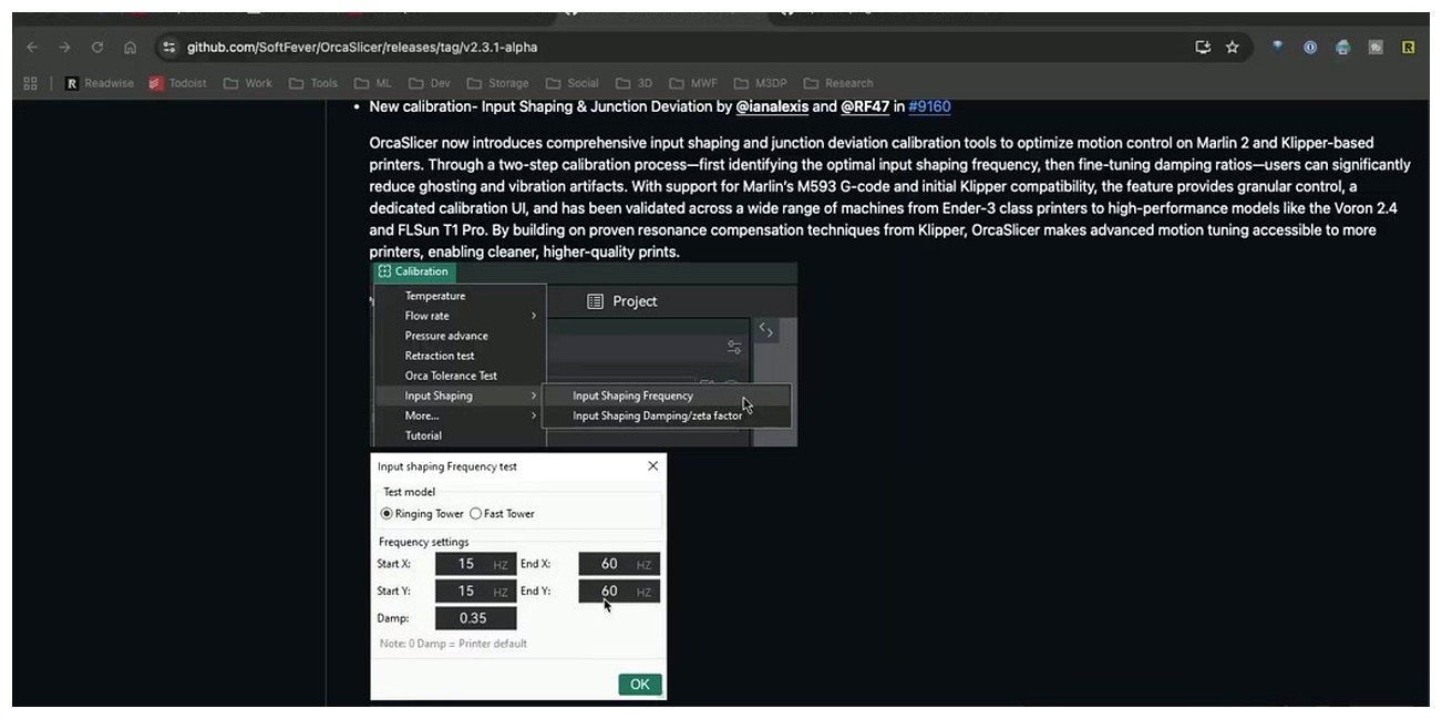
OrcaSlicer 2.3.x: Calibration menu → Input Shaping → Frequency Test. The dialog exposes shaper type, frequency range, and the test model selector.
The calibration is a two-pass tower test. Pass one measures the dominant resonance frequency per axis. Pass two refines the damping ratio once you know the frequency. You run them in that order, because the damping test needs the frequency locked in.
Pass 1: Frequency test setup
Open the Frequency dialog. The fields:
- Test Model: Ringing Tower (recommended) or Fast Tower (shorter, for printers with severe ringing).
- Input Shaper Type: ZV, MZV, ZVD, ZVDD, ZVDDD, EI, 2HUMP_EI / EI2, 3HUMP_EI / EI3, DAA, FT_MOTION, or “Default.”
- Frequency range: defaults 15 Hz to 110 Hz, the wiki recommendation.
- Damping value: 0.0 omits the parameter and lets firmware default fill it in (Klipper falls back to 0.1, Marlin to 0.15). Or enter 0.1 to 0.2 as a manual starting point per the wiki.
Pick the shaper for the first pass by firmware target. Klipper users start on MZV (Klipper’s default, where most CoreXY tunes land). Marlin users pick ZV (only stable choice). On RepRapFirmware 3.4+, OrcaSlicer’s “Default” selection maps to MZV (older RRF below 3.4 maps to DAA). Delta and uncertain users should start with EI, which tolerates frequency error at the cost of more smoothing.
Leave the range at 15 to 110 Hz; narrow it only if a first run lands in a tight zone. Leave damping at 0.0 for the first pass.
Pass 1: Slicing and printing the tower
Click Calibrate and Orca pushes you into slice view with a pre-loaded ringing tower. The slicer interpolates the frequency range across the tower’s Z height, so each band on the wall corresponds to a specific test frequency. The tower runs at deliberately aggressive motion settings; if the print doesn’t excite resonance, banding won’t appear and the test is useless. The wiki recommends roughly 20,000 mm/s² acceleration and 200 mm/s speed.
Warning: those numbers are test-only. The wiki explicitly says, “Restore your 3D Printer settings to avoid keep using high acceleration and jerk values” once you’re done. Don’t leave 20,000 mm/s² in your normal profile or you’ll snap belts and lose steps.
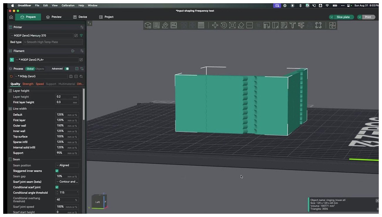
Ringing tower in OrcaSlicer’s slice preview. Each Z band maps to a frequency from the 15 to 110 Hz sweep.
Slice, upload to Moonraker, print. First-layer rules still apply. Total print time on a default tower is 25 to 45 minutes depending on size.
Pass 2: The damping test
After the frequency tower comes off the bed and you’ve identified X and Y frequencies (next section), return to Calibration → Input Shaping → Damping. The dialog locks the frequencies you measured and sweeps damping. Wiki suggests starting in 0.1 to 0.2.
Print, read the smoothest band, log the damping values. Typical answers land 0.05 to 0.20, with 0.1 being the Klipper default. The Klipper docs describe 0.1 as “a good all-round value,” so leaving it there isn’t a sin if the damping tower is ambiguous.
How to read the printed tower
Take the tower off the bed without flexing it. Hold it so a light source grazes the wall at a shallow angle. The ringing bands look like horizontal corduroy in raking light, and the cleanest band is the one where the wall looks smoothest, not the one with the deepest texture. Beginners get this backwards: they pick the band with the strongest visible pattern, but you actually want the band with the least visible pattern.
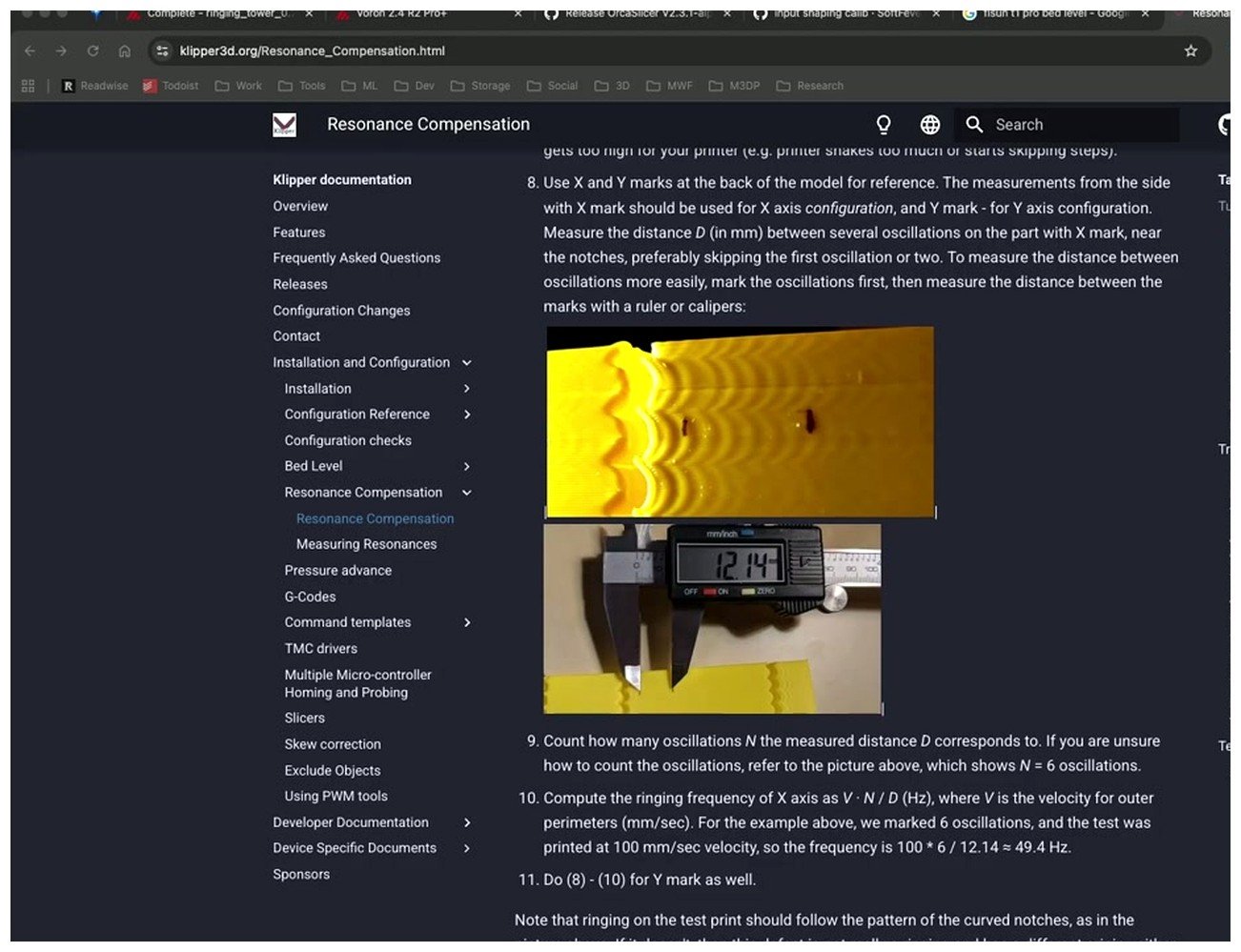
Reading the test result. Klipper’s own resonance docs explain the same physics OrcaSlicer’s tower exposes; calipers help when you want to measure echo pitch directly and confirm the frequency that the band corresponds to.
Look at the X face first (the wall that ran in the X direction during the test). Find the smoothest band. The slicer preview shows the frequency that band’s Z height corresponds to. Note it. Rotate the tower 90 degrees and read the Y face the same way. Almost every machine produces different numbers for X and Y. On a bed slinger like an Ender, the Y axis is the moving bed (heavy, low frequency), so Y commonly lands 15 to 25 Hz below X. On a CoreXY like a Voron the masses move together but the frame stiffness isn’t perfectly symmetric, so X and Y are usually within 10 to 20 Hz of each other but rarely identical.
A handy tiebreaker. If two bands look equally good, pick the higher frequency one. Higher shaper frequency means less smoothing penalty, which means you can push acceleration harder without losing fine detail.
If no band looks clearly best, one of three things happened. Most likely the test acceleration was too low and the print never excited resonance properly. Bump acceleration on the test profile and rerun. Second possibility: filament too matte, ringing is there but you can’t see it. Try silver PLA. Third: there’s an actual mechanical issue masquerading as ringing. The Klipper docs call out a useful test here: if the texture on the tower doesn’t follow the pattern of curved notches in the test geometry, it’s not real ringing. It’s probably under-extrusion, Z-banding, or belt tooth marks, and input shaping won’t touch any of those. Diagnose the extruder or mechanical issue first; our troubleshooting master guide covers the usual suspects.
If the cleanest band is ambiguous and you want sharper resolution, the wiki recommends narrowing the range. Pick the minimum and maximum acceptable frequencies from the first run and repeat the test using that narrower window. The same tower height now sweeps a smaller frequency range, so each band represents a finer step.
Saving results for Klipper
Here’s where I have to be blunt about a misconception. OrcaSlicer does not auto-save your input shaper results to printer.cfg. The calibration menu prints a test, helps you eyeball numbers, and that’s where its responsibility ends. Persisting the values is your job, and there are two clean ways to do it.
Option A: Edit printer.cfg directly (preferred)
Open printer.cfg through Mainsail or Fluidd (Configuration tab, the editor icon next to the file) and add or edit the [input_shaper] section. The full section looks like this:
[input_shaper]
shaper_freq_x: 50.4
shaper_freq_y: 42.1
shaper_type_x: mzv
shaper_type_y: mzv
damping_ratio_x: 0.1
damping_ratio_y: 0.1
A few notes on the syntax. shaper_type (no axis suffix) sets both axes at once. Use the suffixed shaper_type_x and shaper_type_y only when you want different shaper algorithms per axis, which is rare but valid. damping_ratio_x and damping_ratio_y default to 0.1 if you omit them, so you can leave them out unless your damping test gave you something different. Save the file, then either restart Klipper from the Mainsail menu or send FIRMWARE_RESTART from the console.
One pitfall worth flagging. If you’ve ever run SHAPER_CALIBRATE with an ADXL345 in the past, Klipper’s SAVE_CONFIG wrote its own [input_shaper] block to the “SAVE_CONFIG” section at the bottom of printer.cfg. If you now add a second [input_shaper] section higher in the file, Klipper will error out on restart with a “duplicate section” message. Either delete the SAVE_CONFIG version, or just edit the existing one at the bottom and don’t add a new section.
Option B: SET_INPUT_SHAPER in Machine Start G-code
If you’d rather keep the values in Orca’s printer profile (handy when you tune per material or per project), the OrcaSlicer wiki gives a verbatim skeleton for the Machine Start G-code field in Printer Settings:
SET_INPUT_SHAPER SHAPER_TYPE=TYPE SHAPER_FREQ_X=#Xfrequency DAMPING_RATIO_X=#XDamping SHAPER_FREQ_Y=#Yfrequency DAMPING_RATIO_Y=#YDamping
And the wiki’s example, filled in:
SET_INPUT_SHAPER SHAPER_TYPE=MZV SHAPER_FREQ_X=37.25 DAMPING_RATIO_X=0.16 SHAPER_FREQ_Y=37.5 DAMPING_RATIO_Y=0.06
Drop that into Printer Settings → Machine G-code → Machine start G-code, save the profile, and every print sliced by Orca will set the shaper at the start of the job. The catch with this approach: it only applies to prints you launch from Orca. If you upload a G-code file directly to Mainsail and print it, the start G-code Orca embedded still runs, so you’re fine. But if someone else slices a file in PrusaSlicer or Cura and prints it on the same Klipper machine, your SET_INPUT_SHAPER never gets called, and the printer falls back to whatever’s in printer.cfg. That’s why I lean toward Option A as the source of truth and use Option B only for temporary tweaks.
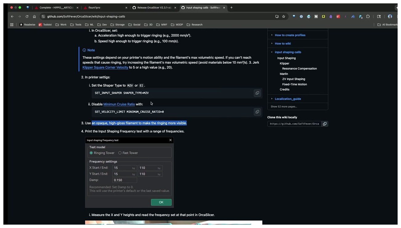
OrcaSlicer’s wiki shows the SET_INPUT_SHAPER skeleton verbatim. The same command works in Mainsail’s console for live tweaks, in Machine Start G-code for per-slice application, or as a direct edit to printer.cfg’s [input_shaper] section.
There’s no special OrcaSlicer profile key that auto-syncs shaper values into Klipper. Persistence lives in printer.cfg or in Machine Start G-code, and that’s the entire menu of options.
Live tweaks from the Mainsail console
While you’re dialing things in, you don’t have to restart Klipper every time you want to test a frequency. SET_INPUT_SHAPER works from the Mainsail console as a one-shot command that applies until the next reset:
SET_INPUT_SHAPER SHAPER_TYPE=mzv SHAPER_FREQ_X=50.4 SHAPER_FREQ_Y=42.1
To disable shaping completely (useful when troubleshooting whether shaping is causing an artifact), set both frequencies to zero:
SET_INPUT_SHAPER SHAPER_FREQ_X=0 SHAPER_FREQ_Y=0
These runtime commands don’t persist. Once you’ve found values you like via live tweaks, edit printer.cfg to lock them in.
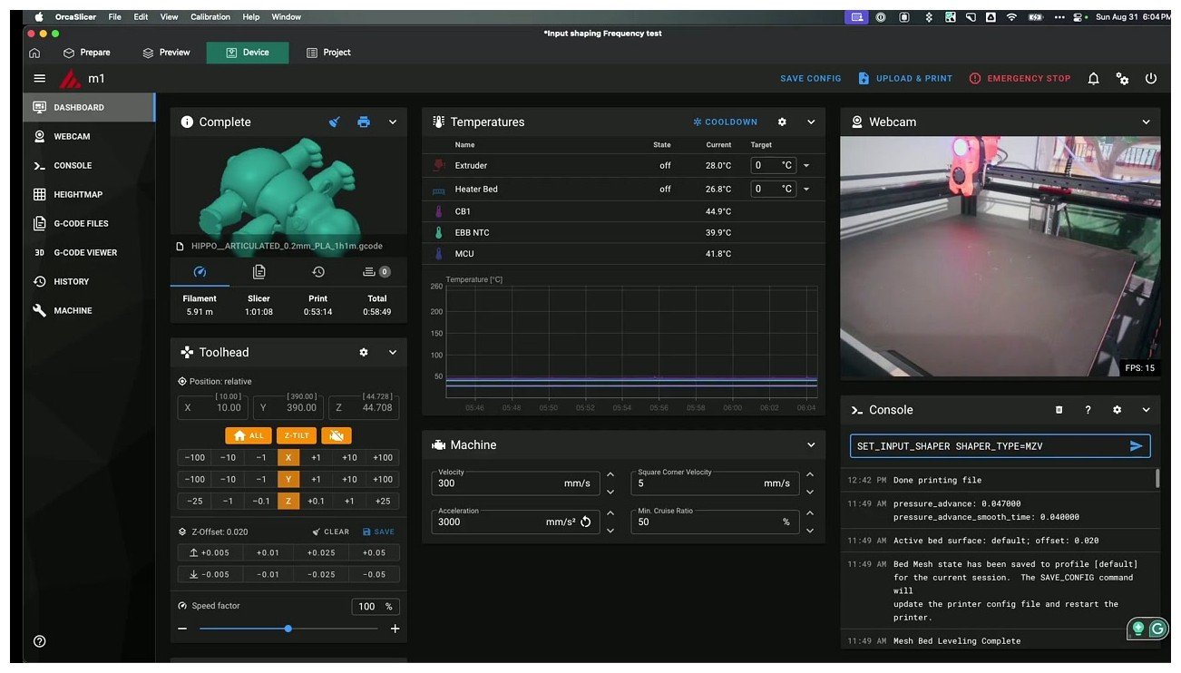
Live testing from the Mainsail console. SET_INPUT_SHAPER is non-persistent, which is exactly what you want while iterating between tower runs.
Saving results for Marlin (M593)
Most readers are on Klipper, but Orca’s calibration produces values that map cleanly into Marlin’s M593 too. The OrcaSlicer wiki skeleton:
M593 X F#Xfrequency D#XDamping
M593 Y F#Yfrequency D#YDamping
M500
Filled-in example:
M593 X F37.25 D0.16
M593 Y F37.5 D0.06
M500
Put those lines in OrcaSlicer’s Machine Start G-code field, or send them once from Pronterface / OctoPrint. The crucial line is M500; that’s what writes values to EEPROM. Without it, the shaper resets on reboot. M593 with no parameters reports current settings, useful for verifying M500 stuck.
Firmware side, Marlin’s Configuration_adv.h needs the right defines uncommented:
//#define INPUT_SHAPING_X
//#define INPUT_SHAPING_Y
#if ANY(INPUT_SHAPING_X, INPUT_SHAPING_Y, INPUT_SHAPING_Z)
  #if ENABLED(INPUT_SHAPING_X)
    #define SHAPING_FREQ_X  40.0   // (Hz) Default X resonant frequency.
    #define SHAPING_ZETA_X   0.15  // X damping ratio.
  #endif
  #if ENABLED(INPUT_SHAPING_Y)
    #define SHAPING_FREQ_Y  40.0
    #define SHAPING_ZETA_Y   0.15
  #endif
#endif
Naming inconsistency that catches people: the firmware define is SHAPING_ZETA_X (zeta is the damping ratio symbol) but the M593 parameter is D. Same value, different label. Marlin’s stock defaults are SHAPING_FREQ_X = 40.0 Hz and SHAPING_ZETA_X = 0.15.
Two hard limits. Marlin input shaping requires a 32-bit board; stock 8-bit AVR Ender 3 / V2 boards can’t keep up with the math. You need an SKR Mini E3 V3 or equivalent. And Marlin’s stable branch only supports ZV; the newer FT_MOTION feature (M493, Marlin 2.1.3+) adds more shapers but is still experimental.
Saving results for RepRapFirmware
Duet users on RRF 3.4 or newer use a slightly different M593 syntax that takes a shaper-type string:
M593 P"ZVD" F37.25 S0.16
On RRF 3.2 and earlier, only the frequency parameter is supported:
M593 F37.25
There’s a real limitation worth knowing: RepRapFirmware currently supports only one frequency for both X and Y axes. The OrcaSlicer wiki spells this out, “RepRap can only set one frequency for both X and Y axes so you will need to select a frequency that works well for both axes.” Practically, that means picking a value in between your measured X and Y frequencies, or the lower of the two if X and Y differ by more than 15 Hz or so. The smoothing penalty on the higher-frequency axis is real, but it’s still better than running unshaped.
Shaper algorithms compared
Klipper supports six shaper algorithms. Note that the OrcaSlicer dropdown lists ten options total: Klipper uses ZV, MZV, ZVD, EI, 2HUMP_EI, and 3HUMP_EI; the other entries route to other firmwares (DAA for RRF, FT_MOTION for Marlin’s experimental motion system, ZVDD and ZVDDD accepted by some forks but not stock Klipper). Picking between them is the single most common question after “what frequency did you measure,” and the answer is mostly a smoothing-versus-tolerance trade-off. The table below pulls the numbers straight from Klipper’s resonance compensation docs.
| Shaper | Duration | Vibration tolerance | Smoothing | When to pick |
|---|---|---|---|---|
| ZV | 0.5 / freq | ±5% (narrowest) | Minimal | Rigid, well-tuned printer with one confidently measured resonance peak. Also Marlin’s only stable choice. |
| MZV | 0.75 / freq | ±4% | Low | Klipper’s default. Most CoreXY machines and well-built bed slingers land here. |
| ZVD | 1 / freq | ±15% | Medium | Slightly more robust than MZV when frequency measurement is uncertain. |
| EI | 1 / freq | ±20% | Medium-high | Delta printers, bed slingers where bed mass changes during the print (full spool to empty), any setup where the resonance frequency drifts. |
| 2HUMP_EI | 1.5 / freq | -40% to +45% | High | Two clearly separated resonance peaks. Don’t enter the resonance frequency directly (see gotcha below). |
| 3HUMP_EI | 2 / freq | -50% to +60% | Very high | Three peaks. Usually means you should fix the machine mechanically before chasing it with shaping. |
Klipper’s own docs are unambiguous about the rule of thumb: “For most of the printers, either MZV or EI shapers can be recommended.” MZV gives you the fastest realistic accelerations with minimal smoothing penalty. EI trades a bit of smoothing for substantially more tolerance, which matters when your resonance frequency wanders (heavier hotend, changing bed temperature, partly-full spool weighing on the gantry).
One gotcha that catches a lot of users on the multi-hump shapers. 2HUMP_EI and 3HUMP_EI shouldn’t be configured with shaper_freq equal to the resonance frequency you measured. Klipper’s docs state explicitly that those shapers are “configured from different considerations to reduce several resonances at once,” meaning the frequency you enter is a tuned center frequency, not the dominant peak. If you ran the OrcaSlicer tower and got 55 Hz, you’d type 55 into MZV or EI directly, but 2HUMP_EI wants a different value derived from your two peaks. Most readers won’t touch these, so don’t worry about it unless your resonance plot shows two distinct peaks of similar amplitude.
If you’re tuning cornering at the same time, remember that junction deviation and square-corner-velocity behave differently once input shaping is enabled. Our OrcaSlicer cornering calibration guide walks through that interaction. Tune input shaping first, then JD.
Typical ballparks per printer family
The numbers below are real values pulled from published configs and forum threads. Treat them as sanity checks (“if my Voron tower says 18 Hz, something is wrong”), not as recipes to copy. Your number depends on belt tension, frame age, toolhead weight, and bed configuration. Measure your own machine.
| Printer family | Shaper | X freq (Hz) | Y freq (Hz) | Notes |
|---|---|---|---|---|
| Voron 2.4 (300/350) | MZV | 55 to 80 | 40 to 60 | Published configs land around 61/43 Hz and 78/58 Hz respectively. Verify on your build. |
| Voron Trident | MZV | 50 to 75 | 45 to 65 | Similar to V2.4, slightly higher Y because the bed is fixed. |
| Ender 3 / V2 (Klipper) | MZV or EI | 40 to 55 | 25 to 40 | Heavy bed pulls Y way down. Verify after every belt change. |
| Ender 3 V3 KE / SE | MZV | 40 to 55 | 30 to 45 | Stock ships with Klipper, frequencies vary by linear-rail variant. |
| Creality K1 / K1 Max | EI (locked) | copied from Y | 55 to 75 | Stock firmware locks EI and only measures Y axis. K1 Max sits slightly lower because of gantry mass. See troubleshooting for the rooted fix. |
| Elegoo Neptune 4 / Pro / Max | auto | 45 to 70 | 45 to 70 | Onboard ADXL345, runs SHAPER_CALIBRATE from the screen. |
| Ratrig V-Core 3 / 4 | MZV | 50 to 80 | 40 to 60 | CoreXY, similar to Voron. ADXL345-driven tuning is the common recipe. |
| Sovol SV07 / SV08 | MZV | 45 to 65 | 35 to 55 | SV08 ships with ADXL345 onboard; SV07 doesn’t. |
For K1 / K1 Max owners specifically, the EI lock in stock firmware is real and frustrating: Creality’s calibration only measures Y and copies the result to X, then forces EI. If you’ve rooted the printer, the community wiki documents how to switch to MZV and measure both axes properly. Our OrcaSlicer K1 / K1 Max guide covers the full setup. Neptune 4 owners can stick with the onboard ADXL routine, but the OrcaSlicer tower is still useful as a sanity check; we cover that in the Neptune 4 guide.
Tower vs ADXL345: when each one wins
If you have an ADXL345 (or LIS2DW) wired to your Klipper host with [resonance_tester] configured, SHAPER_CALIBRATE AXIS=x and SHAPER_CALIBRATE AXIS=y are strictly better than the OrcaSlicer tower for most workflows. The accelerometer pass runs a real frequency sweep, performs an FFT, picks the optimal shaper, and writes results via SAVE_CONFIG. Sub-Hz precision. Minutes instead of an hour.
The FFT method has real downsides too. The frequency sweep exaggerates higher-frequency resonances that don’t get excited at normal print speeds, so Klipper sometimes recommends a high-tolerance shaper (EI) for peaks that wouldn’t affect real prints. The hard back-and-forth moves also stress the printer in ways normal printing doesn’t.
The OrcaSlicer tower’s advantages: free, works on any printer with any firmware that exposes input shaping (including sealed enclosures where wiring an ADXL is a pain), and uses the same motion profile you actually print with. It’s also a great sanity check on accelerometer results; if your ADXL says 65 Hz X but the tower’s cleanest band is at 45 Hz, something’s off and the tower’s usually closer to the truth.
My rule: if you own an ADXL345, use it. If you don’t and you’re not chasing 600mm/s carbon fiber, the tower is good enough. The Klipper measuring resonances doc covers the ADXL wiring if you go that route.
Troubleshooting common results
The questions below come from a few hundred forum threads worth of pain points, paraphrased. Most failures fall into one of these patterns.
“All the bands look the same. I can’t pick one.”
The test didn’t excite resonance, almost always one of three things. Acceleration too low (the wiki recommends 20,000 mm/s² for the test; Orca defaults at 5,000 won’t ring). Filament too matte (silver, white, or any high-gloss pastel shows bands; matte black hides them). Or print speed too slow. Bump acceleration, switch filament, rerun.
“My X and Y frequencies are 20 Hz apart.”
Probably fine. Bed slingers can have 30 Hz gaps because the bed mass on Y is enormous compared to gantry mass on X. CoreXY machines run closer together but rarely match. Use the measured values, don’t average.
“Input shaping made my prints worse.”
Almost always means the wrong frequency got entered, so the shaper is amplifying resonance instead of canceling it. Send SET_INPUT_SHAPER SHAPER_FREQ_X=0 SHAPER_FREQ_Y=0 from the Mainsail console to disable shaping, confirm prints clean up, then re-measure.
“Pressure advance seems off after input shaper.”
Expected. Input shaping changes the acceleration profile the extruder sees, so the previous pressure advance value is now slightly wrong. Rerun the OrcaSlicer pressure advance calibration after dialing in IS. The change is small (a few thousandths) but real.
“K1 / K1 Max is forced to use EI.”
Confirmed. Stock Creality firmware locks the shaper to EI and only measures Y, copying the value to X. The rooted-printer community wiki documents the fix: replace the shipped script with a proper SHAPER_CALIBRATE call that measures both axes. Our K1 / K1 Max guide links to the relevant pages.
“Voron’s not damping fully.”
Mechanical, not tuning. Residual ringing often points to loose foot bolts, resonating panels, or under-tensioned belts. Tighten the frame, check belt pitch, make sure nothing buzzes against the printer. Re-measure.
“My tower doesn’t follow the curved notch pattern.”
Then it’s not ringing. Klipper docs call this out: real resonance follows the test geometry’s notches downstream of corners. Uniform texture unrelated to notches is usually an extruder issue (under-extrusion, Z banding, belt tooth marks); input shaping won’t fix any of those. Run a flow rate calibration first.
“Should I redo input shaper if I add weight to the toolhead?”
Yes. Anything changing the moving mass (heavier hotend, mounted ADXL, ducting, cable chains rerouted) changes the resonance frequency. New belts also count.
When to recalibrate
The wiki’s once-a-year cadence is the baseline. Beyond that, recalibrate after any of: new belts (different tension, different teeth wear pattern); new motors (different inertia); frame moved or relocated (different floor stiffness underneath; my V2.4 changed by 3 Hz after I moved it from a desk to a steel rack); hotend or toolhead swap (mass change); ADXL or cable-chain addition (mass change); or any time you’ve torn down and rebuilt something structural. Skip recalibration after bowden tube swaps, nozzle changes, or build plate changes; none of those affect resonance meaningfully.
Once you’ve got input shaping locked in, it’s worth running the rest of the calibration cluster while you’re in tuning mode. Pressure advance is the obvious next step, because input shaping just changed your acceleration profile. After that, the max volumetric speed test and tolerance fit test round out a properly characterized printer. The temperature tower is the easy entry point if you want a calibration to start with.
FAQ
Does OrcaSlicer save my input shaper results automatically?
No. The calibration runs the test and helps you read the result, but persisting the values is on you. Edit printer.cfg‘s [input_shaper] section directly (preferred) or put a SET_INPUT_SHAPER line in Machine Start G-code.
Can I run input shaping on a stock Ender 3 (8-bit board)?
Not with Marlin; the stock board can’t run the M593 math. Either upgrade to a 32-bit board (SKR Mini E3 V3 or similar) for Marlin IS, or install Klipper, which offloads the math to the host and works on the stock board.
How does the tower method compare to SHAPER_CALIBRATE with an ADXL345?
The ADXL pass is more accurate (sub-Hz precision, automatic shaper selection, full FFT) and faster. The tower is free, works on any printer, and uses real print motion. If you own an ADXL, use it. If not, the tower is good enough for most builds.
What damping value should I start with if I skip the damping test?
0.1. That’s Klipper’s default; the docs describe it as “a good all-round value.” Marlin’s default in Configuration_adv.h is 0.15.
My OrcaSlicer doesn’t have the Input Shaping menu.
You’re on an older release. The feature shipped in OrcaSlicer versions greater than 2.3.2. Update to current stable and the menu appears under Calibration.
Can I tune input shaping per filament?
Technically yes, by putting different SET_INPUT_SHAPER lines in filament start G-codes. In practice, resonance frequency depends on the printer, not the filament. Tune once per machine and leave it.
Related OrcaSlicer guides
- The Complete OrcaSlicer Calibration Guide (Order Matters)
- OrcaSlicer Retraction Test: Solving Stringing in 30 Minutes
- OrcaSlicer Max Volumetric Speed Test: Find Your Hot End Limit (2026)
- OrcaSlicer Cornering & Junction Deviation Calibration (2026)
- OrcaSlicer Z-Wobble & Z-Banding: Diagnose and Fix (2026)