
I’ve slung the same Benchy through nine different OrcaSlicer infill patterns this month, weighing each one and timing it, and the answer to “what’s the best infill” depends entirely on what “best” means for the part. Gyroid is the safe default. It’s also wrong half the time. Here’s the matrix that actually answers the question.
The Sparse Infill Pattern dropdown in OrcaSlicer 2.3.2 lists more than twenty options. Most users only ever need three of them. The other patterns aren’t filler, but they’re tuned for edge cases (shock loading, resin-filled interiors, multi-color flushing, vase-mode shells) that most prints don’t trigger. This guide is the part of the OrcaSlicer settings master guide that tells you which pattern to pick and, just as important, when to ignore the popular advice.
Table of contents
- The 30-second answer
- How OrcaSlicer’s infill actually works
- Decision matrix: pick the right pattern for your job
- Every pattern in the dropdown, explained
- Strength tests: what CNC Kitchen actually found
- Density vs pattern: which one matters more?
- OrcaSlicer-specific settings around the pattern
- Multi-color and flush-into-infill
- Common pitfalls and fixes
- The bottom line
The 30-second answer
If you don’t want to read the whole thing, here’s the short version. I’ve been printing functional jigs and display props on the same machine for two years, and 95% of my parts use one of three patterns.
- Gyroid at 15 to 20% density for any functional part where the load direction isn’t obvious. It’s isotropic (roughly equal strength in every direction), it’s reasonably fast, and it doesn’t fail catastrophically when you push it.
- Lightning at 10 to 15% density for display models, cosplay shells, statues, and anything you don’t plan to drop. It uses about a third of the material of Cubic and prints in roughly half the time. It carries no useful structural load.
- Cubic at 25% for “I have no idea what this part will be used for.” Cubic is the safe coward’s pick. Genuinely isotropic, fast to slice, and it’s been the default in PrusaSlicer-derived slicers forever for a reason.
That covers the vast majority of real-world prints. The other 25-plus patterns exist because edge cases exist: shock loading needs TPMS-FK, multi-color flush-into-infill needs big internal cavities, vase-mode shells use Concentric, and so on. We’ll get to all of them.
If you came here because your slicer is taking forever or your top surface is pillowing, scroll to the pitfalls section. The fix is almost never the pattern itself. It’s a setting next to the pattern.
How OrcaSlicer’s infill actually works
Infill lives under Process > Strength in the prepare panel. The Sparse Infill Pattern dropdown is one of three knobs on that row. The other two (Sparse Infill Density and Sparse Infill Direction) are bigger levers than the pattern in most situations, and we’ll get to that. But for now, this is the screen you’re looking at.
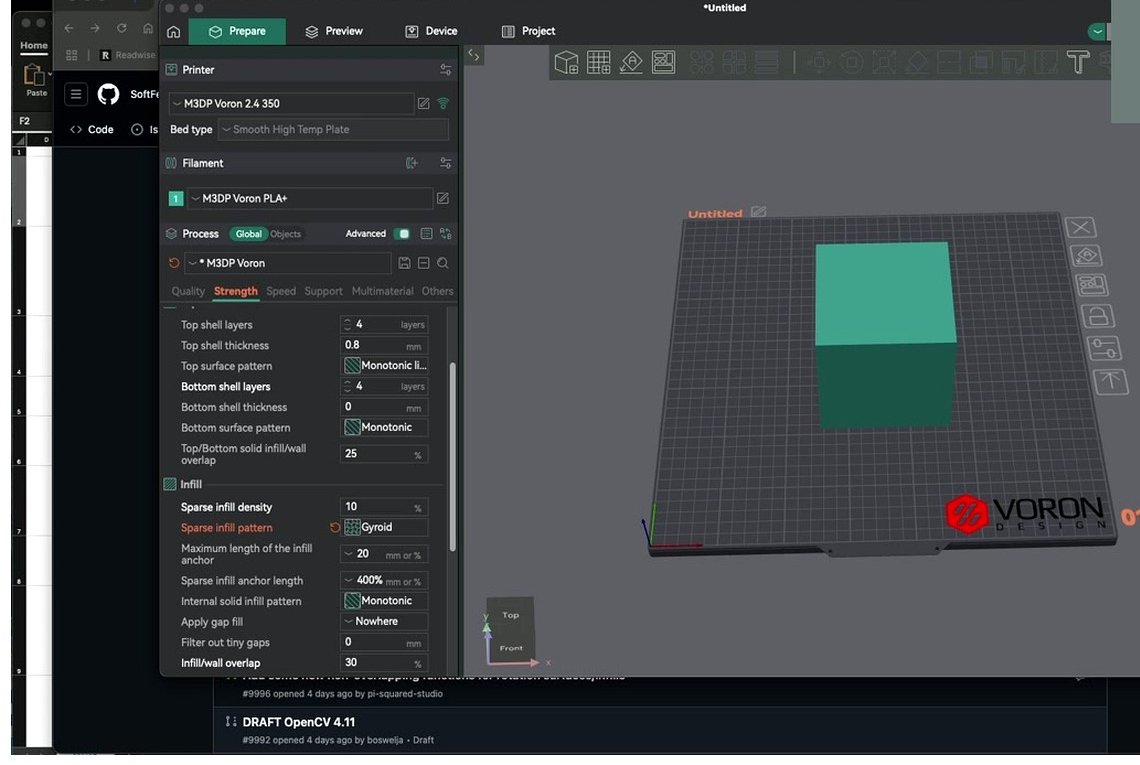
The Strength tab in OrcaSlicer 2.3.2. Density and pattern sit on the same row, but they don’t have equal weight in the final result.
OrcaSlicer actually has three different infill systems running in parallel, and a lot of people miss this:
- Sparse Infill is the patterned interior at less than 100% density. This is the dropdown everyone argues about.
- Internal Solid Infill is the dense fill the slicer drops at 100% density under top layers, above bottom layers, and in transition zones. It has its own pattern dropdown (
internal_solid_infill_pattern), which defaults to Monotonic for wide areas and Concentric for narrow strips. - Top Surface Pattern and Bottom Surface Pattern are separate dropdowns again, controlling only the visible outer faces. Monotonic is the modern default and it’s the right answer almost always.
If your top surface looks bad, you don’t fix it by changing the sparse infill pattern. You fix it by changing the top surface pattern, the number of top layers, or the surface flow. If your part feels weak, that’s the sparse pattern conversation. Keep them straight.
Under the dropdown row sit several settings that matter more than which pattern you pick: Infill Anchor, Infill Anchor Max, Infill Wall Overlap, Infill Combination, and Sparse Infill Direction. We’ll cover those in the OrcaSlicer-specific settings section, but flag this now: tuning anchor and overlap fixes more “weak part” complaints than swapping Gyroid for Cubic ever will.
Decision matrix: pick the right pattern for your job
Here’s the matrix I keep open on my second monitor when I’m slicing. I built it by cross-referencing the OrcaSlicer Patterns wiki with CNC Kitchen’s empirical crush-test rankings and about a year of my own failed prints.
| Job | Primary pick | Backup | Why |
|---|---|---|---|
| Functional, unknown load direction | Gyroid at 20 to 30% | TPMS-D | Truly isotropic, no in-layer crossings, interconnected channels |
| Functional, known unidirectional load | Aligned Rectilinear with direction set to load axis | Cubic at 25% | One strong axis is cheaper than full isotropy when you know the loading |
| Maximum stiffness, time isn’t a concern | Honeycomb at 30% | Triangles at 30% | Highest kg-to-density per CNC Kitchen rankings; pay the print-time cost |
| Speed and material economy with structural duty | Grid at 15 to 20% | Rectilinear | Fastest of the strong patterns; watch for nozzle-drag failures at intersections |
| Display model, no structural duty | Lightning at 10 to 15% | Adaptive Cubic | Lowest material and time; pair with 5 to 6 top layers to fix pillowing |
| Hollow vase or shell | Concentric | n/a | Vase mode bypasses infill anyway; Concentric matches visually for translucent walls |
| Multi-color with flush-into-infill | Cubic, Gyroid, Grid, Triangles at 15 to 20% | Tri-hexagon | Big interior cavities absorb purge; avoid Lightning and Concentric |
| Tall thin part loaded along its long axis | Aligned Rectilinear | Honeycomb | Beam loading benefits from fiber-aligned infill |
| Flexible filament (TPU) | Gyroid or Concentric | Lateral Lattice | Smooth curves deform uniformly; rigid intersections crack flex parts |
| Resin-fillable interior | Gyroid or Archimedean Chords | Hilbert Curve | Continuous interconnected voids let resin flow throughout |
| Shock or impact load | TPMS-FK (Fischer-Koch S) | Gyroid | Bone-like topology designed for energy absorption |
| Large brackets, big interior volumes | Adaptive Cubic | Support Cubic | Densifies near walls only; real material savings without strength loss |
Two notes on how to read this. First, “primary pick” doesn’t mean the only answer. If you’ve been printing Gyroid at 20% for the last six months and your parts hold up, don’t change anything. Second, if your job isn’t on this list, the safest fallback is Gyroid at 20%. I’ve never had Gyroid fail in a way that surprised me.
Every pattern in the dropdown, explained
OrcaSlicer’s wiki lists roughly 28 dropdown options, though the live UI in 2.3.0 was missing a few (issue #10414 documented this). The current 2.3.2 build exposes the full set as far as I can see. Here’s every pattern, organized by family. I’ve kept each entry tight: what it does, when to use it, when not to.
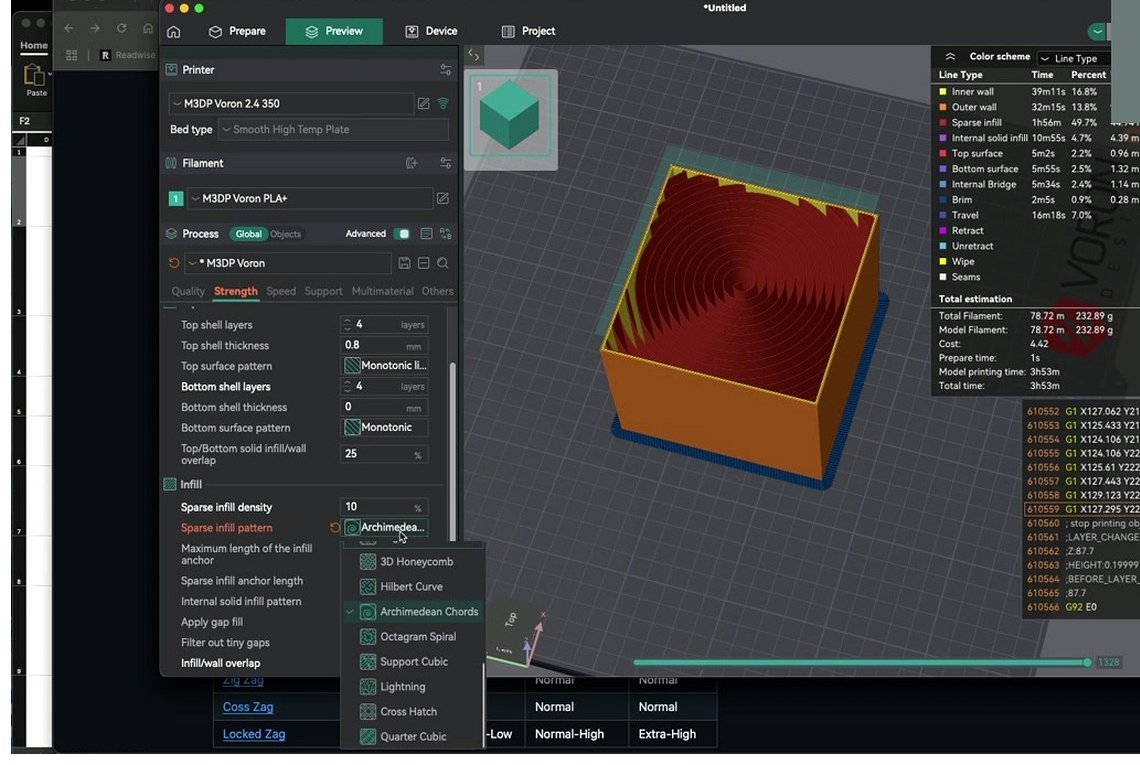
The Sparse Infill Pattern dropdown in OrcaSlicer 2.3.2. There’s the full menagerie. We’re going to walk through all of it.
Linear patterns
Rectilinear. Parallel lines that alternate 0 and 90 degrees between layers. Cheap, fast, weak in Z. Use it for prototypes where you’ll throw the part out anyway. The wiki itself suggests considering Zig Zag instead for slightly better layer bonding.
Aligned Rectilinear. Same lines, but every layer points the same direction. Strong only along the line axis. Set infill_direction to your load axis (a long bracket loaded vertically wants vertical lines). I use this for beam-like parts and almost nothing else.
Line. Slightly rotated parallel lines. Same complaints as Rectilinear. There’s no use case where Line beats Rectilinear cleanly, so I skip it.
Monotonic / Monotonic Line. Rectilinear with smarter path planning so the extruder always moves the same direction across each surface. Sounds boring, but it produces the cleanest top surfaces in the slicer. Use Monotonic as your top surface pattern, not your sparse pattern. It’s wasted on sparse infill.
Zig Zag. Rectilinear-like with a continuous connected path between layers. Reduces travel moves, slightly better layer bonding than plain Rectilinear, same anisotropy. The “default upgrade” from Rectilinear if you don’t care about anything else.
Cross Zag. Zig Zag with per-layer displacement so lines don’t stack vertically. Helps if Zig Zag is causing nozzle drag artifacts on your machine. Wasn’t visible in the 2.3.0 dropdown for everyone (issue #10414); should be there in 2.3.2.
Locked Zag. Zig Zag with a separately tunable skin layer under the top. Independently adjustable skeleton density, skin density, and interconnection size. Useful if you want a hollow-feeling interior with a robust deck under the top surface. Two density values to dial in, so it takes more tuning than other patterns.
Grid and triangle patterns
Grid. Two layers of perpendicular lines stacking into a grid. Fast, stiff, high strength-per-time ratio. The catch: at the overlap points, the nozzle drags over accumulated material. On fast machines this knocks parts loose or causes layer shifts. I’ve lost more prints to Grid than to any other pattern. If your machine is gentle and well-tuned, it’s still a great choice.
Triangles. Three-direction lines forming triangles, with triple overlaps at each intersection. Strong in X and Y, weaker in Z. Same nozzle-drag concern as Grid because of those triple-overlap points. Use it when X-Y stiffness is what you need and you trust your printer.
Tri-hexagon. Triangles offset so intersections form hexagons instead of triple overlaps. Cleaner than Triangles, similar strength, no overlap pile-up. This is my “I want stronger than Cubic but not Honeycomb-slow” pick. Great default for general functional parts.
3D isotropic patterns
Cubic. 3D rotated cube cells with corners pointing down. Loads distribute across all three axes, making it genuinely isotropic. Fast to slice and print. The classic strong default. The only weakness: at low density, the cubes get large and the top layers have long unsupported spans. Bump density to 25% if you see pillowing.
Adaptive Cubic. Cubic that subdivides only near walls (denser near perimeters, sparser in the middle). Real material savings on large parts where the interior carries no load. I use it on tall planters, big brackets, anything with a big internal volume. On small or thin parts, it reverts to dense behavior because there’s no room for the hierarchy.
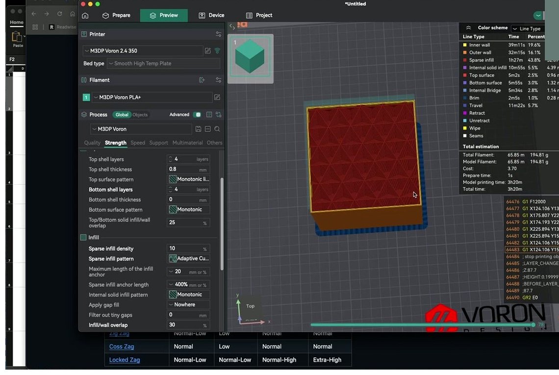
Adaptive Cubic from above. The denser ring around the perimeter is doing the structural work; the sparser center is just keeping the top layers from sagging.
Support Cubic. Cubic that densifies only near the top, sparse everywhere else. Mechanically near-useless but uses very little material and prints fast. For parts where the only job of the infill is to keep the top layer from drooping. Don’t use it for structural parts.
Quarter Cubic. Cubic with extra internal divisions. Marginally stiffer than Cubic, slightly more material. Honestly I’ve never reached for it; the gain over plain Cubic is too small to notice on most prints.
TPMS and curved patterns
Gyroid. Triply periodic minimal surface, the wave-like 3D pattern that’s been the darling of the maker community since 2018. No in-layer crossings (so no nozzle drag), fully isotropic, and interconnected (so you can pour resin in afterward and it’ll flow through). The downside: it’s slow to slice (lots of vertices), and at very low densities (under 10%) the long unsupported spans can buckle and collide with the nozzle on the next layer. Don’t go below 15% with Gyroid.
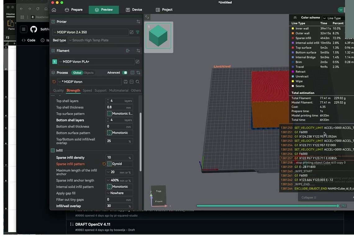
Gyroid in slicer preview at 20%. The wavy shells interlock without ever crossing each other in a single layer, which is what makes it so isotropic and so easy on the nozzle.
Cross Hatch. A linear analog of Gyroid (gyroid-like topology, straight segments). Faster to slice than Gyroid, slightly less strong. The wiki itself notes “consider alternatives for better strength,” which is unusual self-criticism for a slicer’s docs. Use it if Gyroid is too slow on your machine.
TPMS-D (Schwarz Diamond). Another triply periodic minimal surface, diamond variant. Hybrid between Cross Hatch and Gyroid in strength and slice time. Added in OrcaSlicer 2.3.x. I’ve started using it as a Gyroid replacement on functional parts because the slicing is noticeably faster and the strength feels comparable, though I haven’t seen formal CNC Kitchen testing on it yet.
TPMS-FK (Fischer-Koch S). Smooth continuous TPMS that resembles trabecular bone microstructure. Excellent at absorbing shock and vibration. Use it for impact-loaded parts, helmet liners, drone shells, anything that needs to soak up energy without shattering. It’s the slowest pattern in the dropdown to slice, even after the 2.3.2 algorithm optimization.
Honeycomb family
Honeycomb. Hexagonal cells, no in-layer crossings, double walls per hexagon. Maximum stiffness-per-strength of any pattern in the dropdown. The catch is brutal: per Prusa’s docs, the doubled walls cost roughly 25% more material at the same density (worth verifying for Orca’s specific implementation), and it’s the slowest sparse pattern to slice and print. Forum reports show it causes vibration on faster machines. Use it for parts where stiffness matters more than time.
3D Honeycomb. Vertically varying honeycomb made of alternating squares and octagons. The Prusa community has argued for years that 3D Honeycomb is sub-optimal versus regular Honeycomb (more time, no real strength gain). Orca’s implementation inherits the same characteristic. I avoid it.
Lateral Honeycomb. Honeycomb rotated to be vertical (cell axis horizontal) with an overhang-angle parameter. Designed for low-density aero structures. The Orca wiki literally mentions “wings.” Don’t use it for general functional parts; it’ll be weaker than you expect.
Lateral Lattice. Flexible vertical pattern with two adjustable angles. Use for compliant prints where you want directional stiffness, not for normal functional work.
Lightning
Lightning. Tree-like adaptive infill that grows branches only where needed to support the top surface. Provides essentially zero structural value (it’s not designed to). Uses almost no material and prints in a fraction of the time of Cubic. Pair it with 5 to 6 top layers (instead of the usual 3 to 4) to prevent pillowing on the top surface. Quirk: even setting density to 0% with Lightning still triggers infill calculation (issue #11950), surprising users who expect a fully hollow part.
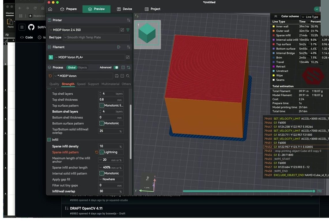
Same cube, Lightning pattern. The tree-like branches grow only where they’re needed to support the top. Beautiful and useless for anything you’re going to load.
Aesthetic and specialty patterns
Concentric. Progressively smaller copies of the outer perimeter, spiraling inward. Use for 100% infill solids, flexible parts (TPU bumpers, RC tires), transparent prints (no in-layer crossings to refract light weirdly), and thin shells. Vase-mode adjacent in feel. Weak to compression perpendicular to the wall.
Hilbert Curve. A continuous space-filling fractal curve. Aesthetically gorgeous through transparent walls. Slow to print due to path complexity, no structural benefit. I’ve used it once, on a transparent acrylic-look display piece, and it’s the only print where Hilbert was the right answer.
Archimedean Chords. Concentric spiral arcs. Saves material versus rectilinear at the same density. Aesthetic or liquid-fillable use only; weak under structural load.
Octagram Spiral. Eight-point spiral pattern with large internal compartments. Aesthetic, weak, slow. Same use case as Hilbert and Archimedean: visible interiors, liquid-fill, flexibility.
Strength tests: what CNC Kitchen actually found
The canonical empirical reference for infill strength comparisons is Stefan Hermann’s CNC Kitchen “Testing 3D printed infill patterns for their strength” video. The original is from 2018 and the rankings have held up remarkably well across slicer updates. The numbers below are paraphrased from his published crush-test results, aggregated by 3D Printscape, and they should be treated as ranges rather than lab-precise figures. (I haven’t independently reproduced these tests; hedge accordingly.)
Per CNC Kitchen testing, on a standardized cube at roughly 25% density, the rough hierarchy was:
| Pattern | Perpendicular crush (kg) | Transverse crush (kg) | Combined avg |
|---|---|---|---|
| Triangle | 358 | 239 | 298 |
| Grid | 354 | 203 | 278 |
| Line | ~338 | 207 | 273 |
| Honeycomb | 343 | 193 | 268 |
| Cubic | 260 | 270 | 265 |
| Gyroid | 260 | ~260 | 260 |
| 3D Honeycomb | ~276 | 230 | 253 |
| Rectilinear | 305 | 195 | 250 |
The headline takeaways from Stefan’s testing, lightly paraphrased:
- The differences between patterns at typical densities (20 to 30%) are smaller than people on Reddit make them sound.
- Adding extra perimeters (more walls) beats almost any infill upgrade for strength gains per gram. If your part feels weak, adding a wall is cheaper than swapping pattern.
- Cubic and Gyroid trade blows depending on load direction. Cubic edges out on transverse load; Gyroid is the most balanced.
- Triangle and Grid win on raw kg numbers but they don’t account for the print-time issues (vibration, nozzle drag) that show up on real machines.
And on print time, again from Stefan’s published comparisons: Gyroid runs about 125% of Cubic’s time, while Honeycomb takes roughly 310% and 3D Honeycomb roughly 288%. So Honeycomb’s small strength advantage over Cubic comes at a 3x time cost. That’s the trade-off the kg-only rankings don’t show.
If you’re going to take one number away from this section, take this: at 25% density, the strongest and weakest patterns in the table differ by maybe 20%. Calibrating your pressure advance properly will move that needle further than swapping infill ever will.
Density vs pattern: which one matters more?
This is the most overlooked point in infill discussions. The pattern matters a lot at low densities and barely at all at high densities. Here’s how I think about it:
| Density | What dominates | What to do |
|---|---|---|
| Below 15% | Pattern geometry | Pick Lightning or Support Cubic for display, Gyroid only if you bump to 15%, avoid Honeycomb |
| 15 to 30% | Sweet spot, patterns converge | Pick by use case from the matrix above |
| 30 to 50% | Density scales linearly with strength | Pattern matters less; consider extra perimeters first |
| 50 to 75% | Diminishing returns | Add walls instead of more infill |
| 75 to 100% | Essentially solid | Pattern affects only print time and surface look |
Below 15% density, pattern geometry dominates. The cell shape and crossover topology determine whether the top layers can bridge cleanly. Lightning and Support Cubic are designed for this regime and shine. Gyroid and Honeycomb start producing long unsupported spans that don’t bridge well; Gyroid in particular has been reported on the Prusa forum to cause print failures at less than 10% because the second-from-top layer has nothing to land on.
Between 15 and 30% is the practical sweet spot, and where most patterns end up within roughly 20% of each other on strength tests. CNC Kitchen’s published numbers all sit in this range. From peer-reviewed PLA tensile testing (PMC and Springer studies, not OrcaSlicer-specific), going from 25% to 50% density adds about 25% strength, but going from 50% to 75% adds only about 10%. Generalize cautiously; numbers vary by material and geometry.
The honest rule of thumb I give people: if you’re carefully picking a pattern, you’re probably under 30% density. Above that, just add walls. Two perimeters at 0.4 mm extrusion width beats almost any infill upgrade for strength per gram, and walls don’t have the geometry penalties that infill patterns do.
OrcaSlicer-specific settings around the pattern
The dropdown is the headline, but the surrounding settings do most of the actual work. Here’s what to dial in.
Sparse Infill Density (sparse_infill_density) ranges 0 to 100%. The wiki warns that not all patterns interpret density the same way; Lightning at 15% is not the same volume of material as Gyroid at 15%. Take the percentage as a directional setting and validate with the slicer’s filament-usage estimate.
Sparse Infill Direction (infill_direction) is in degrees, default 45. You can set a single value or a comma-separated rotation template (e.g., “0,90” to alternate per layer). For Aligned Rectilinear, this is the most important setting in the entire infill block; it determines which axis your part is strong along.
Infill Anchor (infill_anchor) and Infill Anchor Max (infill_anchor_max) connect each infill line to a perimeter with a short segment. Set to 0 to disable (legacy behavior). Percentage values are relative to infill extrusion width. This is the single biggest fix for “infill is not bonded to my walls” complaints. Default values are usually fine; if your infill looks detached from the perimeter in the slicer preview, raise the anchor.
Infill Wall Overlap (infill_wall_overlap) extends the infill slightly into the walls. Recommended 10 to 15%; too high (above 25%) causes over-extrusion bumps visible on the outer walls. Without sufficient overlap, the infill tip stops short of the wall and you get a visible gap in the slicer preview that’ll become a weak boundary in the print. Calibrating your flow rate first matters more here than adjusting overlap, because over-flow at the wall junction creates the same bump symptom.
Internal Solid Infill Pattern (internal_solid_infill_pattern) is a separate dropdown for the 100%-density layers (top layers, bottom layers, transition zones). Defaults to Monotonic for wide areas and Concentric for narrow strips, which is the right answer 99% of the time. If your top surface looks rough, this is a setting to check.
Top and Bottom Surface Patterns are again separate from sparse infill. Monotonic is the default and the right answer. If you want a smoother top, look at ironing settings rather than changing this dropdown.
Infill Combination (infill_combination) prints the sparse infill every N layers at thicker line height, rather than at every layer. This is the trick for making Honeycomb tolerable; combining infill every 2 layers can roughly halve the infill print time. The catch: the combined line height cannot exceed your nozzle diameter. With 3D Honeycomb specifically, combination has been reported (issue #5341) to cause broken paths bridging into empty space, so disable combination for that pattern.
Fill Multiline. Generates parallel extrusion lines for the same line. OrcaSlicer 2.3.2 added improved Clipper2-based overlap handling. Useful for high-flow nozzles.
Gap Fill Target (gap_fill_target) decides where gap fill applies: “Everywhere,” “Top and bottom,” or “Nowhere.” Everywhere gives maximum strength at the cost of more squish in thin slivers. Top and bottom is the safe default.
Multi-color and flush-into-infill
If you’re running multi-color (AMS, MMU, manual swaps), OrcaSlicer can dump the purge from filament changes into the model’s own sparse infill instead of the wipe tower. This is the flush_into_infill setting, and it’s a big material saver, but it interacts strongly with the pattern you pick.
The mechanic: when the slicer changes color, it normally extrudes purge onto the wipe/prime tower until the new color is clean. With flush-into-infill on, that purge gets routed into the model’s own sparse infill cells instead. The bigger the unbroken interior volume per cell, the more purge you can absorb before the slicer gives up and triggers a wipe-tower change.
Patterns that work well for flush-into-infill: Cubic, Gyroid, Grid, Triangles, Tri-hexagon. All have substantial internal cavities. Patterns to avoid: Lightning (almost no internal volume to dump purge into), Concentric (channels follow walls, so purge color shows through if the walls are translucent), dense Honeycomb (small cells, mixed colors get spread thin and can become visible).
One hard constraint: flush-into-infill requires the prime tower to be enabled. The OrcaSlicer wiki explicitly says it will not take effect without it. The full mechanics, tower sizing, and edge cases are covered in the wipe and prime tower deep dive, which is the mandatory companion read for this section. There’s also a broader multi-color printing guide that walks through AMS-specific concerns.
One more visibility note: if your outer walls are printed in a transparent or translucent filament, the mixed-color purge inside the infill will be visible from outside. Use opaque walls or accept the look as a feature.
Common pitfalls and fixes
These are the failure modes I see most often on the OrcaSlicer subreddit and the Bambu Lab forum. None of them are exotic; almost all of them have a fix that doesn’t involve switching pattern.
Gyroid failing at low density. Symptom: the print fails halfway up, or the second-from-top layer collides with the nozzle. Cause: Gyroid at less than 10% density produces unsupported spans that buckle. Fix: raise density to 15% minimum, or switch to Cubic if you want to stay at 10%. Don’t go below 15% with Gyroid as a rule.
Honeycomb slicing super slow. Symptom: the slicer takes minutes to compute infill on a small part. Cause: Honeycomb has the most complex path generation in the dropdown. Fix: enable Infill Combination (every 2 layers) to roughly halve the slice and print time, or switch to Tri-hexagon for similar stiffness with cleaner slicing.
Lightning pillowing on top. Symptom: top surface looks dimpled or droopy over the infill gaps. Cause: Lightning is sparse by design and doesn’t support the top layers as well as a regular infill pattern. Fix: increase top layers from the default 3 or 4 to 5 or 6, and consider raising top surface flow slightly.
Infill not bonding to walls. Symptom: the infill looks detached from the perimeter in the slicer preview, or the part splits along the wall-to-infill boundary under load. Cause: low Infill Wall Overlap, zero Infill Anchor, or under-extrusion. Fix: set Infill Wall Overlap to 10 to 15%, confirm Infill Anchor is non-zero (default is fine), and make sure your flow rate calibration is correct.
Grid causing layer shifts on fast machines. Symptom: random layer shifts or knocked-over parts on a Bambu X1, Voron, or other fast printer. Cause: nozzle drag at Grid’s perpendicular intersections accumulates material and catches. Fix: switch to Cubic or Gyroid, both of which have no in-layer crossings.
Infill pattern affects slicing even at 0% density. Symptom: you set sparse infill to 0% with Lightning selected expecting a hollow part, but the slicer still computes Lightning paths. Cause: known quirk (issue #11950). Fix: change pattern to anything other than Lightning when you actually want zero infill.
3D Honeycomb breaking with Infill Combination. Symptom: the slicer generates broken paths bridging into empty space when combining 3D Honeycomb across layers. Cause: documented in issue #5341. Fix: disable Infill Combination for 3D Honeycomb specifically, or switch to plain Honeycomb.
For symptoms that don’t fit any of the above, the broader OrcaSlicer troubleshooting guide walks through the diagnosis process. Material choice also influences which infill pattern works best; flexible filaments and high-temp engineering plastics behave differently, and the filament settings reference covers material-specific overrides.
The bottom line
There is no best infill pattern. There’s a right one for the job, and the job determines the pattern, not the other way around. For functional parts where you don’t know the load direction, Gyroid at 15 to 20% is the safe default. For display models, Lightning at 10%. For “I have no idea what this part will do,” Cubic at 25%. Those three cover almost everything most people print.
If you’re spending an hour deciding between Gyroid and TPMS-D, you’re optimizing the wrong thing. Spend it calibrating pressure advance and flow rate, or fixing your seam placement, or dialing in tree supports for the next overhang. Those settings move the quality needle further than infill choice ever will. And when you’re done with all of that, come back to the settings master guide for the rest of the OrcaSlicer cluster.
Print the matrix above, tape it next to your monitor, and move on with your life. Your parts will be fine.
Related OrcaSlicer guides
- OrcaSlicer Settings Master Guide: Every Setting Explained (2026)
- OrcaSlicer for Elegoo Centauri Carbon: Setup and Best Settings
- OrcaSlicer for Snapmaker Artisan, J1 and 2.0: Setup Guide
- OrcaSlicer for Creality CR-10 Series: Profiles and Setup Guide
- How to Install OrcaSlicer on Linux: AppImage, Flatpak, AUR