The first time I noticed pillowing on a print I cared about, it was a Bambu X1C running 0.2 mm layers with 15% gyroid infill, default Bambu Studio profile imported into OrcaSlicer 2.3.0. The model was a desk organiser my partner had asked for, in a colour I didn’t have a second roll of. I pulled it off the bed, ran my thumb across the top, and felt little raised lumps in a perfect grid pattern, like braille spelling out “you didn’t set enough top layers.” Three solid layers had not been enough to bridge the gyroid cells underneath. I had to print it twice.
That single print is why I have strong opinions about top surfaces, and why I keep coming back to OrcaSlicer’s settings menu instead of trusting a vendor profile. The slicer has more top-surface-relevant levers than any free option I’ve used, and most of them sit unexplored in tabs hobbyists never open. If your tops are pillowing, ghosting, gapping, scarring, or coming out of an ironing pass looking worse than before, the fix is almost always inside Quality, Strength, or the per-filament cooling panel. You don’t need to switch slicers. You need to know which six or seven settings do the work.
I’m writing this on OrcaSlicer 2.3.0 stable, with 2.3.2 in nightly RC as of this week. A few of the most useful top-surface improvements (Fixed Ironing Angle, per-filament ironing, bridge density above 100%) only landed in 2.3.2-rc2, so I’ll flag those clearly. The 2.3.0 advice still works on the stable build.
What “bad tops” actually means, five distinct defects
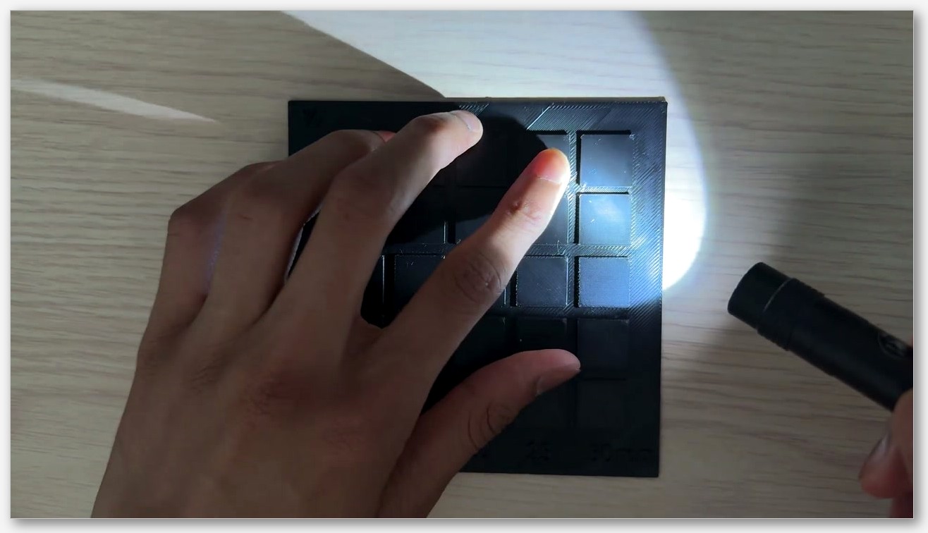
Most posts about “rough top layer” lump every defect together. They aren’t the same problem, and the fix is different for each. Before changing a single setting, spend five seconds identifying which of the five you’re actually looking at. I usually tilt the print under a desk lamp so the light grazes across the top, throwing every height variation into shadow. Phone flashlights work too if you hold them low and to one side.
Pillowing, the lifted blob between infill cells
Pillowing looks like rows of small domes or dimples spread across the top, often matching the underlying sparse infill (gyroid blobs, grid intersections, crosshatch nodes). You sometimes see hairline splits at the centre of each dome where the skin has cracked open. The print otherwise looks finished, but the surface feels lumpy.
The physics is straightforward. The top skin has to bridge each open cell of the sparse infill below. Where the strand crosses air, only surface tension and rapid cooling stop it from sagging. If the air on that strand is too warm or there’s too little of it, the plastic stays soft, shrinks as it cools, and curls upward. The next pass smears across the curl. The result is a lifted blob. The cause is the same on Bambu, Prusa, and Creality printers because it’s thermal rather than slicer-specific.
Infill telegraphing, the lattice ghost in your top
Telegraphing is the cousin of pillowing that looks subtler at a distance and worse up close. The top sealed surface looks closed and smooth from one angle, but rotate it under light and you see ridges, dimples, or a lattice ghost where the sparse infill below has shown through. Run a fingernail across it and you can feel the height differential, even though there are no visible holes or splits.
This is also a bridging problem with a different failure mode. The strand cools faster over the void than over the rib of infill, so it sits slightly lower over the void and slightly proud over the rib. The remaining differential becomes visible under raking light. The fix is more top shell layers, denser infill, or both.
Gaps between top infill lines, slim parallel slits
This one is easy to spot. It produces visible parallel slits on the top, often running the full length of the surface in the direction of the top infill extrusion. The slits are usually narrower than a hair and you can sometimes see through them to the layer below. They’re not the rectangular voids of infill telegraphing; they’re the missing space between two extrusions that didn’t merge.
The root cause is under-flow, not insufficient layers. The top surface line width is set too narrow for the spacing the slicer chose, or surface flow ratio sits below what the printer needs to bridge adjacent lines into a continuous skin. There’s also a small family of OrcaSlicer bugs that can leave thin slits even when flow looks right (covered below).
Rough, scarred, or zit-covered tops
This is the catch-all bucket for tops that look like the printer wandered while working. You see visible toolpath lines as ridges, dots where the nozzle pressed material as it changed direction, alternating diagonal stripes from the ironing pattern flipping every layer, or specks of plastic where a retraction left a scar.
These are flow-and-motion problems rather than thermal ones. Pressure advance is off, top surface speed doesn’t match outer wall speed, the Z-seam is landing on a visible face, the wall-loop direction is forcing a sharp corner where there shouldn’t be one, or small-area flow compensation is over-correcting. Each has its own fix; they’re rarely solved by one master setting.
Ironing artefacts, banding, melt-back, blobs
If you turned ironing on hoping it would smooth a rough top and the result looks worse, you’re seeing one of three classic ironing failures. Banding means the surface has visible stripes where each ironing pass left its own ridge. Melt-back means the iron pass dragged extra material into a valley that wasn’t there before. Blobs at the start of each ironing line mean the nozzle dribbled while waiting to start the next pass.
Ironing is a slow, low-flow pass that smooths the top by re-melting the surface and dragging a small amount of additional plastic across it. The settings are unforgiving. Too much flow and you get blobs. Too little and the pattern stays visible. The wrong angle and you get tiger stripes.
 How OrcaSlicer handles top surfaces in 2.3.x
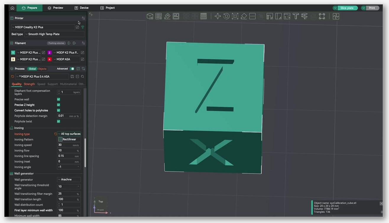
OrcaSlicer scatters its top-surface controls across four tabs, which is the first reason new users miss half of them. Once you know where to look, the layout is logical.
Where the settings live
The Quality tab holds line width, ironing, wall and surfaces (one-wall-on-top, wall loop direction, avoid crossing walls), and small-area flow compensation. This is where most cosmetic decisions are made. The Strength tab carries the structural ones: top shell layers, top shell thickness, top surface density, top surface pattern, top-bottom infill wall overlap, and the sparse infill choices that telegraph into the top. The Speed tab has top surface speed and ironing speed. The Material (filament) tab carries all the cooling settings, including “Keep fan always on”, the slow-down-for-layer-cooling toggle, and the per-feature fan overrides.
If your defect is thermal (pillowing, splitting, anything that gets worse on tall thin parts), start in Material. If it’s structural (telegraphing, gaps, voids), start in Strength. If it’s cosmetic (pattern lines, zits, ironing bands), start in Quality. Speed is usually a finishing tweak, though top surface speed is one of the few speeds I’d set consciously rather than letting it inherit from outer wall.
What changed in 2.3.2 vs 2.3.0
The 2.3.2 nightly carries the largest set of top-surface improvements OrcaSlicer has shipped in a single release. From the v2.3.2 release notes, the most relevant items are:
- Fixed Ironing Angle. The ironing direction can now be locked to a specific angle on every ironed layer, instead of alternating. This kills tiger-striping.
- Per-filament ironing parameters. Flow rate, spacing, inset, and speed can be set on each filament profile rather than once per process. Useful when you print PLA and PETG with the same machine.
- Ironing angle changed to relative offset. The Angle Offset value is now relative to the top-surface fill direction instead of an absolute angle. Setting 0° means “follow the fill direction”; 45° means “rotate the ironing 45°.”
- Individual feature flow rates. First layer, outer walls, inner walls, overhangs, infill, gap fill, supports, and support interfaces all have their own flow adjustment fields. Fix a single defect without changing temperature.
- Multiline infill rebuilt with smoother continuous extrusion and up to 10 line patterns, affecting how the layer below the top behaves.
- Wall-connected infill. Multiline patterns now connect to perimeter walls instead of to each other. Less likely to leave loose strands the top has to bridge.
- Bridge density can exceed 100%, meaning tighter line spacing for the bridged top extrusions. The closest thing to a single-toggle anti-pillowing setting that 2.3.2 ships with.
- Narrow-area filling for non-linear solid patterns, which fills strips near walls that previously stayed empty.
- Bug fix: an infinite loop with zero top solid infill density has been resolved. Setting top surface density to 0 used to lock the slicer; it no longer does.
None of this is in 2.3.0. If your tops give you persistent grief and you’re on stable, it’s worth grabbing the 2.3.2 nightly, running a calibration cube on a copy of your profile, and seeing whether Fixed Ironing Angle or higher bridge density alone fixes your issue. Keep 2.3.0 around as a fallback. My own 2.3.2-rc2 install crashed twice in the first week, both times when I was switching printer profiles.
Default sparse pattern is now Crosshatch
One 2.3.0 change affects telegraphing even though it isn’t strictly a top-surface setting. The default sparse infill pattern is now Crosshatch instead of Grid. Crosshatch lays down two offset diagonals in a way structurally similar to gyroid but cheaper to compute. For top surfaces, the cell openings the top has to bridge are smaller and more uniform than grid produced. If you’re upgrading from 2.2.x and haven’t changed your sparse pattern manually, your tops should look slightly better on the new default.
Fixing pillowing
Pillowing is the most photogenic top-surface failure and the easiest to diagnose. You can feel it. You can see it from across the room. And it almost always means one of three things: not enough cooling, not enough top shell, or sparse infill too sparse for the top above it. The fix order matters. Adding shell layers without fixing cooling buys you a slightly thicker bad surface.
Diagnose first, feel the print and look across the light
Before changing anything in the slicer, pick up the failed print and feel the top. If the lumps are firm, rounded, and arranged in a regular pattern matching the sparse infill below, it’s pillowing. If the lumps are random and crusty, it’s probably zits or a stringing fragment dragged onto the top. If the surface is smooth to the touch but you see a lattice ghost under raking light, it’s telegraphing.
Cooling first, settings second
Open the Material tab and check three settings. Keep fan always on should be enabled if your filament tolerates it (almost all PLA, most PLA-PETG blends; not ABS, not most polycarbonate). Slow printing down for better layer cooling should also be on. No cooling for the first can sit at 1 or 2 layers; that’s a bed-adhesion setting and doesn’t affect tops directly.
The fan itself needs to be high during the top layers. On a stock part-cooling fan, 100% during the top three or four layers is normal for PLA. If you’re on a printer with weak part cooling (looking at every Creality Ender 3 derivative with the stock duct), an aftermarket duct does more for tops than any slicer setting. The wiki lists every cooling field on its material cooling reference.
One bug to watch. Issue #12858 on the OrcaSlicer GitHub reports that “Keep fan always on” causes “Force cooling for overhangs” to be ignored. The issue was filed against 2.3.1 and is still showing as open against 2.3.2-rc2 in my testing, so if your overhang cooling looks weak after enabling always-on fan, you’ve probably hit the bug rather than a config error. Check the issue tracker before assuming it still applies to whatever version you’re running; it may be patched in a later build.
Increase top shell layers and top shell thickness
The Strength tab has two related settings that both increase the solid sealed cap. Top shell layers sets the number of solid shell layers including the surface layer. The default in most profiles is 3 or 4. For a part you care about, 5 to 6 is reasonable. Top shell thickness is a fallback; solid layers are increased during slicing if the thickness calculated from shell layers is thinner than this value. In practice that means if you switch to a thinner layer height, the thickness setting kicks in and adds more layers automatically.
I keep top shell thickness at 1.0 mm. At 0.2 mm layer height that’s 5 layers; at 0.16 mm it’s 7. Shell layers I leave at 5. Defaults from most vendor profiles are too thin for ambitious infill densities. A 10% gyroid with 3 top layers is asking for trouble.
Raise sparse infill density and consider a smaller cell pattern
If your top layers can’t bridge the infill cells beneath them, you have two options: thicker top, or smaller cells. Both work. Smaller cells are usually cheaper in plastic. Raising sparse infill density from 15% to 20% with a gyroid pattern often fixes mild pillowing without adding a single shell layer.
Pattern matters too. Grid leaves square cells easy to bridge across one axis and hard across the other. Gyroid leaves curvy, more uniform cells. Crosshatch (the new default in 2.3.0) has smaller, more frequent cell openings than grid. If you’re stuck on grid, raise the density. If you can switch patterns, gyroid or crosshatch at 15% will outperform grid at 20%.
Drop top surface speed
The Speed tab has top surface speed, which the wiki recommends setting similar to the outer wall speed for a smoother and higher-quality finish on visible surfaces. Most vendor profiles set it to the inner wall speed by default, which is too fast. On my Bambu profile I dropped it from 200 mm/s to 80 mm/s and the pillowing vanished on the same gyroid sparse pattern I had been fighting. Slower extrusion gives the fan more time per millimetre of strand, which is the same as more cooling without changing fan speed at all.
This is the cheapest pillowing fix because it doesn’t add a single solid layer. The cost is print time, which goes up only on the top three or four layers since this is the only speed it controls. On a typical decorative print, the time penalty is one or two minutes.
If it persists, drop nozzle temp 5°C and recheck
If you’ve raised top shell, raised infill density, lowered top surface speed, and pillowing persists, the next move is a small drop in nozzle temperature. Hotter plastic stays plastic longer; if you can drop 5°C without losing layer adhesion, top strands solidify faster and pillowing reduces. Run a temperature tower to find the lowest reliable temperature for your filament; our OrcaSlicer temperature tower guide walks through how to set one up.
Temperature is the last lever because under-temp produces its own failures (poor layer adhesion, weak parts, brittle infill) and you need to know your filament’s working range first.
Fixing infill telegraphing
Telegraphing is sneakier than pillowing because it survives a casual inspection. You only see the lattice when light hits the print at the right angle, and by then the print is in someone’s hands. The fix is similar to pillowing but the priorities shift: top shell becomes more important and cooling becomes less important.
Top shell layers vs top shell thickness, which one actually controls it
I see people online recommending one or the other interchangeably, and they’re not interchangeable. Top shell layers sets a fixed count. If you change layer height, the cap thickness changes proportionally. Top shell thickness sets a minimum in millimetres; the slicer adds layers if needed to hit it. For telegraphing, you want the thickness setting to drive the calculation, because the height differential the lattice produces needs a certain absolute thickness of solid plastic to average out. Three layers at 0.28 mm layer height is 0.84 mm. Three layers at 0.12 mm layer height is 0.36 mm. The same lattice shows through both differently.
Starting point: top shell thickness 1.0 mm, top shell layers 4 to 5. Whichever produces more layers wins. The print takes longer at fine layer heights, but so does everything else, and if you’re slicing at 0.12 mm you presumably care about the finish.
Match infill cell size to top shell count
The other half is the cell size of the sparse infill below. If you have 5 solid top layers and your sparse pattern is grid at 5% density, the grid cells are large enough that even 5 layers will telegraph faintly. Either raise density (about 15% gyroid or 18% crosshatch as a rule of thumb) or switch to a smaller-cell pattern. Gyroid and crosshatch both have shorter unsupported spans than grid for any given density, which is why I default to gyroid for parts where the top matters.
Bridge density above 100% in 2.3.2
The 2.3.2 release notes describe bridge density extending above 100%, with tighter spacing between bridge lines for better bonding and less sagging. This is directly relevant to telegraphing because the first solid top layer is bridged across the sparse infill cells; closer-spaced bridge lines means less sag per cell and a flatter starting surface for the layers above. I’ve been testing at 110% bridge density on a PLA print with 10% gyroid sparse infill and the lattice ghost is noticeably reduced. The trade-off is slightly more plastic in the bridging layer, but it’s confined to one layer.
If you’re still on 2.3.0 stable, this option isn’t there. The workaround is to raise sparse infill density slightly or thicken the top shell. Neither is as targeted as the new bridge density slider, which is one of the better reasons to run the nightly.
Pattern choice, Monotonic Line vs Hilbert for hiding lattice
The OrcaSlicer wiki on top and bottom shells recommends Monotonic Line for top surfaces. It follows an ordered single-direction path that minimises tool-head jumping and the resulting witness marks. Monotonic is similar but uses a path layout that avoids overlapping with the perimeter, reducing excess material at joints, though it may introduce visible seams and increase print time.
Hilbert Curve is the wild-card option that fewer people use. The wiki notes its intersecting, continuous paths provide tight interlayer connections that reduce surface collapse and voids, at the cost of much slower print time. On telegraphing-prone prints (low-density sparse, thin top shell, large flat area), Hilbert is better than Monotonic Line at hiding the lattice underneath, because its constantly changing direction means no two adjacent strands run parallel for long. The downside is a 30-50% time penalty on the top surface.
If the top is the whole point of the print (a sign, a faceplate, a lid), Hilbert is worth the time. Otherwise, Monotonic Line is the right default.
Surface flow ratio, small drops, big visual changes
The surface flow ratio in Quality > Wall and Surfaces affects the amount of material extruded on top or bottom solid infill. The OrcaSlicer wall and surfaces wiki page suggests decreasing it slightly for a smoother surface finish. Actual flow is surface flow ratio times filament flow ratio times object flow ratio if set, so this stacks with normal flow calibration.
A drop from 1.0 to 0.96 reduces over-extrusion at line crossings without leaving visible gaps between adjacent lines, and it can be enough to take a faintly telegraphed top into “looks solid” territory. Treat it as a fine-tune rather than a primary lever. Calibrate flow first with a proper pressure-advance pass (our PA Line vs PA Pattern guide covers both methods), then nudge surface flow ratio as a final polish.
Closing gaps between top infill lines
The “thin parallel slits” problem is the most counter-intuitive of the five defects because it looks like over-extrusion (visible toolpath) when it’s actually under-extrusion (lines not merging). Most people respond by lowering flow, which makes the slits worse.
Top surface line width 100-105%, why over-extrusion is not the answer
The OrcaSlicer wiki recommends a top surface line width of 100-105% of nozzle diameter, framed as the value recommended for smooth results without over-extrusion. For a 0.4 mm nozzle that’s 0.40 to 0.42 mm. The default in most profiles is 0.4 mm flat (100%). If you’re seeing slits, push to 0.42 mm (105%) before doing anything else.
Why this matters. Lines need to overlap slightly to merge into a continuous skin. If the slicer spaces lines at exactly the nominal width, nozzle tolerances and slight under-flow leave a hair-width gap between adjacent lines. A 5% wider line eats that tolerance, and it doesn’t produce over-extrusion because the slicer adjusts spacing to match. For context, outer wall sits at 105-120% in most profiles, inner wall is 120%+, sparse infill is around 115%, internal solid infill around 110%. Top surface is deliberately the narrowest because you want the line to flatten without piling up.
top_bottom_infill_wall_overlap, 25-30% as a starting point
The wiki notes that Top/bottom infill wall overlap is slightly enlarged to overlap with walls for better bonding, with 25-30% suggested as a starting point. This controls how far the top infill extends into the perimeter wall. Too low, you get a visible ring of gap right at the edge. Too high, you get a ridge of over-extruded plastic where the infill rams into the wall. Default is usually 16-18%; bumping to 25% closes edge gaps on most printers without producing visible bulges.
Only one wall on top, when it helps and when it backfires
The Only one wall setting tells OrcaSlicer to use only one wall on flat surfaces, giving more space to the top infill pattern. Especially useful in small features like letters. On a flat top with small details (text, a logo, a thin face that needs to look clean), this can dramatically improve the surface because the slicer has more room to lay continuous infill lines instead of squeezing them between two walls.
It can also backfire. On a part with high curvature or many small islands, single-walling the top produces weak spots and inconsistent infill at the wall junction. I use it for flat-topped boxes, faceplates, and signs, not for organic shapes or thin-walled containers. The threshold subsetting that controls when the rule triggers is conservative enough by default that it rarely fires where it would cause problems.
Known bugs to watch, and the gap-fill fallback
Two OrcaSlicer issues affect this defect specifically. Issue #124 reports that gap infill runs after solid infill in certain geometries, producing ridges on top surfaces. The bug has been around for a while and surfaces most often on parts with mixed solid and partial top layers. If you see ridges running perpendicular to the rest of the top infill, this is probably the cause. Issue #12030 reports that inner wall line width can interact with gap infill to produce thin slits when the inner wall is set wider than usual. If you’re running 130%+ inner wall width and getting slits, drop the inner wall to 120% and see if they close.
If top surface density is at 100% and you still have visible slits, the cause is almost always one of: line width too narrow, surface flow ratio set below 1.0, or the slicer chose a pattern that doesn’t pack lines tightly at the geometry’s particular angle. Try Monotonic Line, top surface line width 105%, surface flow ratio 1.0. That combination clears the slits on every print I’ve thrown at it. If they persist, you may be looking at under-extrusion that goes beyond the top surface, in which case see our piece on OrcaSlicer under-extrusion symptoms and fixes.
Fixing rough, scarred, or zit-covered tops
“Rough top” catches everything that isn’t pillowing, telegraphing, gaps, or ironing artefacts. The fixes are scattered across more settings than any other defect, which is why so many troubleshooting posts feel like a checklist of unrelated tweaks. They aren’t unrelated; they all attack the same problem (inconsistent flow plus inconsistent motion), but each fixes a different mechanism.
Top surface speed should match outer wall speed
I mentioned this in the pillowing section because it doubles as a cooling fix. It’s also a finish fix on its own merits. The wiki notes that top surface speed is usually set similar to the outer wall speed to achieve a smoother and higher-quality finish on visible surfaces. Most profiles inherit top surface speed from the inner wall (typical 250 mm/s on a Bambu profile), which is too fast for a clean visible finish. Drop it to outer wall speed (typical 80-150 mm/s) and the toolpath visibility on the top reduces immediately.
Z-seam, retract scars, and wall loop direction
If your top has small specks or zits that look like the printer paused there, they’re either Z-seam dribbles (start-of-line blobs from inadequate pressure advance) or retract scars (where the nozzle pulled back and residual pressure pushed a dot of plastic out as it moved). For Z-seam, move the seam off the visible surface using OrcaSlicer’s seam-position controls. Our walkthrough on hiding the Z-seam covers how to do that without changing the print orientation.
For retract scars on top surfaces, the relevant trick is “Avoid crossing walls” in Quality > Wall and Surfaces. If retracts are landing on the top because the toolhead is hopping across without lifting, enabling avoid-crossing-walls forces the slicer to route around perimeters instead of through them, eliminating most cross-surface retracts. The cost is slightly longer travel time. Wall loop direction controls whether the slicer prints inner walls before outer walls and which direction it traverses each loop. For small flat-topped features where the seam where infill meets perimeter is leaving a visible ring or zit, try flipping wall loop direction. It’s a free experiment.
Small Area Flow Compensation and PA calibration
Small-area flow compensation reduces flow on very short extrusion segments to prevent the pressure buildup that produces blobs at the start of a short line. The 2.3.2 release notes describe an improved curve that prevents spike artefacts when values are closely spaced. If you’re on 2.3.0 and seeing small zits or blobs on short top segments (near letters, near small islands), the 2.3.2 nightly’s revised curve is one of the cleaner fixes.
Pressure advance affects every visible surface, including the top, because it controls how quickly extrusion ramps up and down at the start and end of every line. If your top has visible dots at line starts, raised ridges where lines change direction, or thin patches where lines end, pressure advance is mis-tuned. Calibrate it before chasing any other top-surface fix.
Ironing without ruining your top
Ironing is the OrcaSlicer feature that can turn a good top into a great one or a fine top into a mess. It works by running a second very slow pass at very low flow across the top surface, re-melting the strands and dragging a small amount of fresh plastic across the gaps. When it works, you get a satin finish. When it doesn’t, you get bands, blobs, or melted divots.
When to iron, when not to
Iron when the top is flat, the filament is well-behaved at low flow (PLA and PLA matte are the gold standards), the part-cooling fan is good enough to solidify the ironing pass within a few seconds, and you’re not in a hurry. Skip ironing when the top is textured by design, when the filament is PETG (often produces inconsistent ironing), when you’re printing ABS without an enclosure, or when the print’s top is small enough that ironing’s setup overhead doubles the print time. For a balanced read on ironing including filament-by-filament behaviour, the Upside Parts surface quality test is the cleanest comparison I’ve seen.
Ironing Type, the four numbers, and the wiki’s clogging warning
The Ironing Type setting controls which layers get ironed. Top Surfaces irons every layer the slicer considers a top surface, including intermediate top layers on stepped geometries. Topmost Surface only irons the final top layer, which is what you want for a desk organiser or any single-elevation flat top. All Solid Layers irons every solid layer including bottoms and internal solid layers, which is almost never what you want; it adds enormous print time for invisible improvement. Default to Topmost Surface unless your model has multiple flat tops at different heights.
The four numbers from the OrcaSlicer ironing wiki page:
- Pattern. Concentric or Rectilinear. Rectilinear is faster and produces consistent banding (which Fixed Ironing Angle can hide); Concentric follows the perimeter and looks more handmade. For most flat tops, Rectilinear with Fixed Ironing Angle in 2.3.2 is my default.
- Flow. Amount of material extruded during ironing, expressed as a percentage of normal flow. Lower is smoother but risks under-coverage; higher gives better coverage but risks over-extrusion. Common starting point: 10% for PLA, 8-10% for PETG, 12-15% for matte filaments that need a bit more to flow.
- Line Spacing. Distance between ironing lines. Wiki recommends equal to or less than nozzle diameter, so 0.4 mm or less for a 0.4 mm nozzle. I run 0.1 mm for high-detail ironing and 0.2 mm for routine use.
- Inset. Distance from the perimeter where ironing stops. Set to 0 to extend all the way to the wall.
The wiki warns that ironing increases the risk of heat creep and potential clogging because of the slow filament movement through the hotend. This is a real risk on extruders with weak heatsinks or marginal cooling. If your prints start clogging mid-iron and the symptoms cleared up when you turned ironing off, this is what happened.
Fixed Ironing Angle and per-filament overrides in 2.3.2
Pre-2.3.2, ironing alternated direction between layers by default, so a multi-layer ironing pass laid down crisscrossed paths. The visible result was tiger striping. The new Fixed Ironing Angle option locks the angle on every ironed layer. The release notes suggest 0° and 90° with the default 45° infill direction. I run 0° on rectilinear ironing and the tiger stripes vanish.
OrcaSlicer 2.3.2 also moves ironing flow, spacing, inset, and speed onto the filament profile in addition to the process profile. You can have one process called “Standard Top Surface Iron” and have PLA, PETG, and matte PLA each carry their own ironing flow without three separate processes. For PETG specifically, the Upside Parts test showed ironing leaves visible lines remaining. Drop ironing flow to 8-10%, set Topmost Surface only, and accept the result will not be quite as smooth as PLA.

A 30-minute top-surface tuning workflow
If you have one evening and a roll of filament you don’t care about, here’s the order to run a fresh tuning pass. The goal is to isolate which setting is doing the work, so you don’t end up with five changes from the default and no idea which one helped.
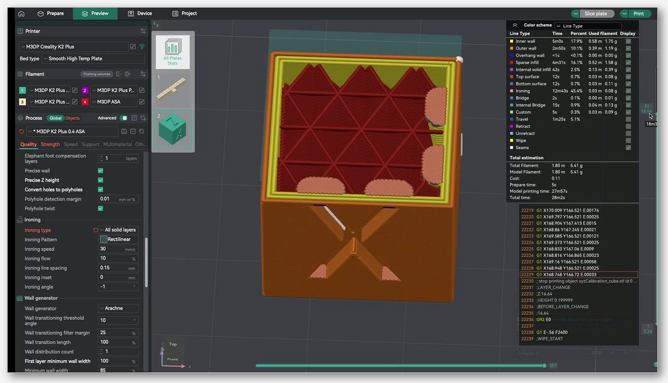
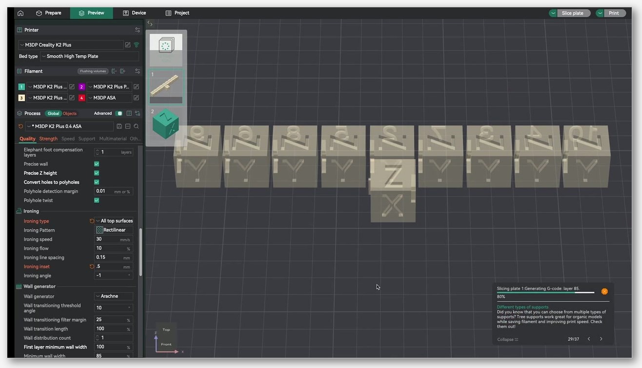
Print a 40 mm cube with default profile
Open OrcaSlicer, load a 40 mm cube, apply your vendor-default process profile, slice, print. Don’t touch anything. The point is a baseline you can compare against. Photograph the top under raking light from a desk lamp held low and to one side. Save the photo with a filename that includes the settings.
Tweak in this order, one change per print
Change one setting per print, in this priority order:
- Cooling. Keep fan always on, fan at 100% during top layers, slow-down-for-layer-cooling enabled.
- Top shell. 5 layers and 1.0 mm thickness as a starting point.
- Top surface speed. Match outer wall speed.
- Pattern. Monotonic Line as default. Try Hilbert if telegraphing persists.
- Ironing. Only after the un-ironed top looks clean.
The reason for this order is that ironing is a finishing pass. If your un-ironed top has pillowing, ironing will smooth the pillows into glossy pillows. Fix the underlying defect first. Run one change. Print. Photograph. Compare to the previous photo at the same angle. Most slicer-side defects are clearly identifiable from a side-lit photo, and the photo log becomes a reference you can come back to next time you change filament or printer.
When to stop and accept “good enough”
There’s a point where additional tuning produces diminishing returns. If you’ve done the cooling, top shell, speed, and pattern fixes, and your top is clean to the touch and doesn’t show a lattice under raking light, you’re done. Don’t keep tweaking ironing flow in 1% increments looking for a satin finish. Real-world tops have a finish that’s “fine for the job” rather than “lab-grade smooth,” and time spent chasing the last 5% is time you could spend printing something else.
Filament-specific notes
PLA and PLA matte
PLA is the easiest material to print clean tops with, and matte PLA is the easiest of the easy. The matte additives scatter light slightly, hiding minor surface imperfections that show on glossy PLA. The Upside Parts ironing test found PLA matte to be the cleanest result with ironing, which lines up with my own experience. If you’re trying to nail a top finish for a portfolio shot or a gift, matte PLA at 5 to 6 top shell layers with Topmost Surface ironing at 10% flow is hard to beat. Standard glossy PLA also irons well, but every imperfection shows.
PETG, needs different ironing flow and spacing
PETG is the troublemaker. Its higher viscosity means the strand doesn’t flatten as cleanly as PLA, and re-melting it during an ironing pass leaves visible lines even when flow looks correct. For PETG tops, my approach is: fan slightly lower than PLA (50-60% on top layers instead of 100%, because PETG layer adhesion suffers with full fan), top shell layers 5 to 6, top surface speed at outer wall speed, ironing flow 8 to 10%, ironing spacing slightly wider than PLA at 0.25 mm, Topmost Surface only. The result is not as smooth as PLA but it’s noticeably better than ironing PETG with PLA-tuned settings.
ABS, ASA, and TPU
ABS and ASA tops are fine without ironing if the enclosure is doing its job. The Upside Parts test reported ABS extrusion failed after the first ironed layer due to cooling sensitivity, which matches my experience: ABS does not like being slowed to ironing speed in an enclosed chamber because heat builds up in the nozzle. Skip ironing entirely and rely on slow top surface speed, the fan-off-on-bridges trick, and a moderate part-cooling fan during the top layers only.
TPU has its own family of top-surface issues, mostly thanks to gap fill behaviour. Issue #2414 on the OrcaSlicer tracker reports that gap fill produces small bulges on TPU that telegraph into the next solid layer. The workaround is to disable gap fill on TPU profiles and accept a slightly less perfect wall in exchange for a cleaner top. For most TPU prints, the top doesn’t matter enough to fight gap-fill behaviour. Ironing TPU is a non-starter; the material is too elastic to re-melt cleanly.
FAQ and where to download OrcaSlicer 2.3.2
How many top layers should I use for a 0.2 mm layer height?
Five is a safe default. Three is the minimum that survives most sparse patterns at 15%+ density. Six is the comfort zone for low-density sparse (10% or less). Set top shell thickness to 1.0 mm and let the slicer pick the higher of (5 layers, 1.0 mm). If you change layer heights frequently, the thickness setting keeps the cap consistent while the layer count adjusts.
Does ironing work on textured tops?
No. Ironing assumes a flat surface that can be re-melted into smoothness. If you’ve used Fuzzy Skin or any deliberate texture on the top, ironing will flatten the texture into a half-melted compromise that looks worse than either ironed flat or textured. Pick one.
Is Monotonic Line always better than Monotonic?
For most prints, yes, because Monotonic Line minimises tool-head jumps and produces a cleaner, more uniform finish. Monotonic has its uses on prints where the seam where infill meets perimeter is causing visible joint marks; its slightly different path layout avoids overlapping the perimeter, at the cost of longer print time and occasional visible seams in the field.
Why is my ironing pass leaving zits at the start of each line?
Pressure advance under-tuning. The nozzle dribbles while waiting to start the ironing line, then dumps the extra plastic when motion starts. Calibrate PA before tuning ironing. Beyond that, lowering ironing flow by 1-2% sometimes helps if the dribble is borderline.
Can I iron PETG?
Yes, but expect a less clean result than PLA. Use Topmost Surface only, drop flow to 8-10%, widen spacing to 0.25 mm, and accept that visible lines may remain. PETG’s viscosity is the limit, not your settings.
What’s the difference between top surface pattern and density?
Pattern controls the shape of the path the slicer draws to fill the top. Density controls how packed those lines are; 100% means a solid fill. For a sealed top, density should be 100%; setting it lower leaves visible voids.
Where do I download OrcaSlicer 2.3.2 nightly safely?
From the official OrcaSlicer releases page on GitHub. Look for the 2.3.2-rc or 2.3.2-beta tagged builds; the stable 2.3.0 is also listed and is the right choice if you don’t want nightly bugs. I run both: 2.3.0 on my main machine, 2.3.2-rc2 on a second laptop for testing. Avoid mirror sites; the GitHub link above is the only source I’d trust. orcaslicer.net is a third-party reference; we don’t host binaries.
Once installed, run a flow and pressure-advance calibration with whatever filament you’ll be tuning tops with. Top-surface tweaks are sensitive to the underlying flow; getting those right makes every later adjustment more reliable. Then come back to the workflow section, print a 40 mm cube, photograph the top under raking light, and start changing one setting per print until the top looks how you want it. If your prints still don’t look right, it’s almost always hardware: worn nozzle, loose belt, weak fan duct. Slicers can’t save bad hardware. They can make good hardware look great.
Related OrcaSlicer guides
- OrcaSlicer Troubleshooting: Master Index of Every Common Fix
- OrcaSlicer Bed Adhesion Problems: Glue Strategies & Real Fixes (2026)
- OrcaSlicer Print Stops Mid-Print: Causes and Recovery Guide
- OrcaSlicer Print Time Estimate Wrong: Why and How to Fix
- OrcaSlicer Retraction Test: Solving Stringing in 30 Minutes